Librecad
Содержание:
- Basic Editing
- Редактирование объектов
- Руководство по эксплуатации на русском языке
- Circle
- Select
- Command-line
- Создаем эскиз транспортира: часть 2
- LibreCAD Review
- Modify
- Curve
- Polyline
- История
- Системы координат
- The Coordinate System
- Ellipse
- Как установить LibreCAD на Ubuntu и производные?
- Что такое чертеж
- Рабочий лист и навигация по нему
- Description
- Графика и фото (Портативные) » LibreCAD 2.1.3 Portable
- Dimensions
Basic Editing
Entities can be inserted, selected, and, once selected, can be deleted, transformed or duplicated. To insert an entity means to draw it by selecting the appropriate drawing tool, such as line, arc, etc. from the main CAD toolbar (see image below), and by locating points that define the object to be drawn, such as the endpoints of a line.
1.Show line tools
2.Show circle tools.
3.Show polyline tools.
4.Draw points.
5.Insert text.
6.Create hatch.
7.Show modify tools.
8.Create block.
9.Show arc tools.
10.Show ellipse tools.
11.Draw splines.
12.Show dimension tools.
13.Insert image.
14.Show info tools.
15.Show selection tools.
Редактирование объектов
Вроде бы наша центральная окружность построена, но выглядит наш чертеж из-за самопересечений неправильно. Но не стоит расстраиваться, исправить эту ситуацию с помощью инструментов редактирования LibreCAD несложно.
Для начала воспользуемся одной из самых мощных функций редактирования — выравниванием: Изменение -> Выровнять. После запуска функции приглашение в командной строке поменяется — нам предложат выбрать ограничивающей объект. Нажмем на левую часть малой дуги. Приглашение командной строки теперь укажет выбрать объект для выравнивания. Нажмем на верхний отрезок линейки в месте, находящимся левее дуги. В результате действия функции отрезок будет выровнен с дугой. Завершим действие функции (двойной Esc).
Что же, теперь самопересечений у нас нет. Однако выравнивание отрезка по дуге оголило правую часть линейки. Для того, чтобы быстро поправить ситуацию без дополнительных построений воспользуемся функцией зеркального отражения: Изменение -> Зеркально отразить
Обратите внимание, что после активации функции содержание панели инструментов изменилось — теперь там находятся функции для выбора объектив, а приглашение командной строки гласит о необходимости выбора объектов для зеркалирования. Если вы предварительно выбрали отрезок, то вам не требуется совершать никаких действий
Если же нет, выберите его и нажмите клавишу далее на панели инструментов, или же клавишу Enter на клавиатуре.
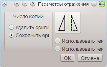
Теперь нам будет предложено указать первую точку на линии симметрии. С помощью позиционирования по центрам укажем точку в центре окружности. Теперь переключимся на позиционирование по средним точкам (snap to middle points) и в качестве второй точки середину одной из больших дуг транспортира. После указания второй точки выскочит окошко, спрашивающее о параметрах зеркалирования. Нам следует указать, что оригинал нужно сохранить. а остальные функции нам пока не интересны. В результате действия функции у нас появится зеркальная копия отрезка, которая заполнит пустое пространство.
Что же, внесем финальный штрих в геометрическое строение транспортира — сделаем его углы скругленными. Для таких операций в LibreCAD имеется специальная функция: Изменение -> Скругление. После активации функции нам будет предложено указать первый объект. Однако, не будем торопится, для начала в панели свойств укажим радиус — 2, а таке активируем галочку, гласящую об усечении линий.
Руководство по эксплуатации на русском языке
Как пользоваться программой? Сначала поясним, что собой представляет чертеж в принципе. Чертеж — это геометрическая модель некого объекта на двухмерной плоскости. От рисунка он отличается четкостью, строгостью и простотой. Чертеж представляет собой два слоя: однородная поверхность (чертежный лист) и слой чертежа с объектами.
Все эти объекты имеют четкую геометрию и образуют два типа параметров:
- геометрическое строение;
- координаты.
Компьютерные чертежи позволяют добавлять большое количество параметров, а гибкость заключается в том, что эти параметры можно постоянно менять.
При первом запуске программа позволит вам выбрать язык интерфейса и фон для чертежей.

Навигация по рабочей поверхности
- Курсор перемещается по листу, если зажать среднюю кнопку мыши.
- Зум осуществляется скроллингом мыши.
- При масштабировании листа сетка координат автоматически масштабируется с коэффициентом 10. Поэтому блоки объединяются в 10×10.
- Система координат бывает локальная и и глобальная. Локальная — задает точки координат относительно любого места на поверхности. Глобальная- ориентир, который не дает потеряться в бесконечном листе чертежа.
Разберем, что такое примитив. Примитив — это различные базовые объекты типа отрезков, окружностей, дуг, текстовых строк. Далее этими элементы могут компоноваться в более сложные объекты-блоки.
Для примера попробуйте создать по двум точкам. Сделать это можно разными способами:
- Выберете кнопку на панели инструментов line tools и нажмите соответствующую иконку.
- В меню выбрать «Draw -> Line -> Line from 2 points».
- Введите в командной строке слово «line».
После этих действий панель инструментов изменится, и вы сможете активировать простейшую привязку. При нажатии на кнопку мыши точка автоматически появляется по данной привязке.Таким образам можно сделать несколько удобных для вас привязок, чтобы было проще выполнять задачи.
Кроме примитивов вы можете создавать эскизы. Вы можете взять изображение, которое вам нужно начертить и посредством наслоения примитивов, образовывать блоки. А уже их можно размещать произвольное количество раз, используя различные характеристики: размер, цвет, местоположение, угол.
Во многом работа в программе librecad похожа на ручное черчение. На бумаге, чтобы создать вид или план, нужны карандаш и линейка. В librecad подобные инструменты есть.
Плюсом является то, что в любой момент пользователь может изменить параметры и характеристики, чтобы поменять чертеж проекции.
Частой ошибкой пользователей является вера в то, что удастся сразу создать чистовой вариант, без вспомогательных линий и точек. Но этого не стоит боятся, в программе достаточно элементов, которые помогут очистить опорные линии и объекты, которые в финальной версии чертежа не нужны.

Безусловным плюсом является то, что софт абсолютно бесплатный и поддерживает самые популярные операционные системы.
Эта программа будет полезна не только инженерам или архитекторам. Рядовой пользователь сможет построить план квартиры или отдельной комнаты, который можно будет распечатать для дальнейшего использования.
Circle
Centre, Point {DrawCircle}: Draw a circle with a given radius by assigning a centre point and a point on the circumference.
Centre, Radius {DrawCircleCR}: Draw a circle with a given radius centred at an assigned point.
2 Points {DrawCircle2P}: Draw a circle with a given diameter by assigning two opposite points on the circumference.
2 Points, Radius {DrawCircle2PR}: Draw a circle with two points on the circumference and with an assigned radius.
3 Points {DrawCircle3P}: Draw a circle assigning three points on the circumference.
Concentric {DrawCircleParallel}: Draw a circle concentric, with the same centre point, to an existing circle.
Circle Inscribed {DrawCircleInscribe}: Draw a circle inside an existing polygon of four sides or more.
Tangential 2 Circles, Radius {DrawCircleTan2}: Draw a circle tangential to two circles with a given radius.
Tangential, 2 Circles, 1 Point {DrawCircleTan2_1P}: Draw a circle tangential to two existing circles and assigning a centre point to establish the radius.
Tangential, 2 Points {DrawCircleTan2}: Draw a circle tangential to an existing circle and define the diameter and placement by assigning two points on the circumference.
Tangential, 2 Circles, Radius {DrawCircleTan2}: Draw a circle tangential to two existing circles with a given radius.
Tangential, 3 Circles {DrawCircleTan3}: Draw a circle tangential to three existing circles and/or lines.
Select
Select Entity {SelectSingle}: Select, or deselect, one or more entities (default cursor action).
Select Window {SelectWindow}: Select one or more enties enclosed by selection window (L to R), or crossed by selection window (R to L) (default cursor «drag» action).
Deselect Window {DeselectWindow}: Deselect one or more enties enclosed by selection window (L to R), or crossed by selection window (R to L).
(De-)Select Contour {SelectContour}: Select or deselected entities connected by shared points.
Select Intersected Entities {SelectIntersected}: Select on or more entities crossed by selection line.
Deselect Intersected Entities {DeselectIntersected}: Deselect on or more entities crossed by selection line.
(De-)Select Layer {SelectLayer}: Select or deselected all entities on the layer of the selected entity.
Select All {SelectAll}: Select all entities on visible layers (-).
Deselect all {DeselectAll}: Deselect all entities on visible layers (- or default action).
Invert Selection {SelectInvert}: Select all un-selected entities will deselecting all selected entities.
Command-line
Since 2.1.0:
- Command-line output is automatically copied when highlighted.
- Keycode mode was reintroduced as a toggle in Application Preferences -> Defaults (requires restart)
Keycode mode automatically accepts 2 character commands.
In other words, you don’t need to press enter.
Since 2.2.0:
- A new button with a drop-down menu has been added to the command-line
- Keycode mode was rewritten and the toggle is now accessed by the new command-line button.
Toggling keycode mode no longer requires restarting LibreCAD.
If a 2 character command is not recognized, you can continue with a longer command.
- Spacebar now accepts commands like Enter.
- The ‘cal’ command now toggles a calculator mode.
- Multi-command input can be separated by semicolons: ci;0,0;10
- Command files (command input separated by newlines) can be loaded from the new command-line button
- Multi-command input can be assigned to a variable; values can also contain variables (they are read recursively)
a=ci;0,0;10
b=ci;10,0;10
c=\a;\b;kill
\c
- A variable file can be set to load at startup via Application Preferences -> Paths -> Variable File
- Relative coordinates such as @10,20 can also be written as 10..20 (allowing for keypad input)
Создаем эскиз транспортира: часть 2
Отлично, первая часть работы сделана. Перейдем к созданию дуги траспортира. Для этого воспользуемся построением дуги по центру, точке и углам (найти ее можно в разделе дуги панели инструментов).
Панель инструмента с разделами примитивов
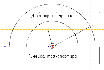
После инициализации создания дуги в командной строке появляется приглашение в вводу «Укажите центр». Как видно из рисунка транспортира, центр дуги распологается на середине верхней стороны линейки. Чтобы спозиционировать центр таким образом, выберем привязку по центрам «Snap to center points». Теперь подведем курсор к области середины верхнего отрезка и когда он приклеется к центру отрезка нажатием кнопки мыши зафиксируем центр. Приглашение командной строки вновь изменится — теперь предложено указать радиус. Что же, согласно приведенному выше чертежу, радиус малой дуги составляет 30 мм, его и вводим:
30
Теперь необходимо будет поочередно ввести начальный и конечный угол (соотвественно 0 и 180 градусов). После создания первой дуги LibreCAD предложит указать центр новой дуги.

Позиционирование центра дуги
Это нам подходит — снова указываем ту же точку в качестве центра.
Затем вводим радиус равный 50 мм. Чтобы немного разнообразить процесс создания укажим углы с помощью автоматических привязок. Для этого выберем привязку по конечным точкам. Теперь подведем курсор к правому верхнему углу линейки транспортира и укажим первый угол дуги. Аналогично, второй угол определим указанием левого верхнего угла линейки
Обратите внимание, что дуга строится по часовой стрелки от начального угла к конечному.
Указание начального угла дуги
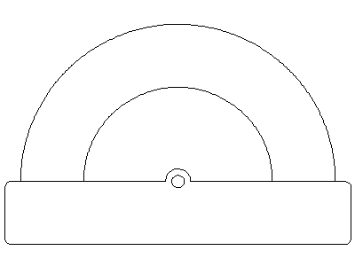
Что же, эскиз готов! Скачать мой эскиз можно .
LibreCAD Review
If you have been looking for a way to increase your 2D design capabilities, then LibreCAD should definitely be on your short list of software options. There are simply too many advantages to an investment in LibreCAD to overlook it — let’s go over a few.
It is Free!
The number one reason that LibreCAD has gained a foothold in the marketplace is its status as the premier free program in the space. This may be the first reason that people come to it, but it is definitely not the last. Free means nothing if the product does not help you design anything. However, this is what makes this tool so advantageous for digital designers without a huge budget. LibreCAD is the training program for many designers without an established presence because they can start designing professionally with no layout of resources. The program is also an industry standard because of its flexibility, so any design made with this program can be moved into outside projects, even AAA professional projects. It uses the AutoCAD DXF file format, meaning you lose no compatibility whatsoever.
It is Opensource!
LibreCAD is always expanding thanks to the efforts of designers just like you. Although you may get more defaults and presets built into a pay program, you get the same thing for free with just a little bit of searching for LibreCAD add-ons. The process is also a great learning experience if you are a relatively new designer. You learn much more about the 2D design process looking under the hood instead of having the entire world given to you without an explanation.
Has Built In Tutorials!
Furthering its reputation as the premier lead in program for new designers, LibreCAD comes equipped with an easy mode. All that you have to do is hover over virtually any feature to receive a detailed explanation of it in a small window. There is no better tool for learning, which is why LibreCAD is actually the preferred software for many 2D design classrooms.
LibreCAD Functions Like Programs You Know!
The best part about this program is that it uses many control and UX techniques that have been made commonplace in widely used programs like Adobe Photoshop and the Word Office suite. You will find familiar symbols and keyboard shortcuts leading you into a day-one usability that gets people pumped to move into advanced aspects of the program.
Modify
Attributes {ModifyAttributes}: Modify the common attributes of one or more selected entities, including Layer, Pen color, Pen width, and Pen Line type.
Delete {ModifyDelete}: Mark one or more entities to be deleted, press to complete operation.
Delete selected {ModifyDeleteQuick}: Delete one or more selected entities.
Delete Freehand {ModifyDeleteFree}: Delete segment within a polyline define by two points. (Use «Snap on Entity» to place points.)
Move / Copy {ModifyMove}: Move a selected entity by defining a reference point and a relative target point. Optionally keep the original entity (Copy), create mulitple copies and / or alter attributes and layer.
Revert direction {ModifyRevertDirection}: Swap start and end points of one or more selected entities.
Rotate {ModifyRotate}: Rotate a selected entity around a rotation point, moving the entity from a reference point to a target point. Optionally keep the original entity, create multiple copies and / or alter attributes and layer.
Scale {ModifyScale}: Increase or decrease the size of a selected entity from a reference point by a defined factor for both axis. Optionally keep the original entity, create mulitple copies and / or alter attributes and layer.
Mirror {ModifyMirror}: Create a mirror image of a selected entity around an axis defined by two points. Optionally keep the original entity and / or alter attributes and layer.
Move and Rotate {ModifyMoveRotate}: Move a selected entity by defining a reference point and a relative target point and rotataing the entity at a given angle. Optionally keep the original entity, create mulitple copies and / or alter attributes and layer.
Rotate Two {ModifyRotate2}: Rotate a selected entity around an absolute rotation point, while rotating the entity around a relative reference point to a target point. Optionally keep the original entity, create multiple copies and / or alter attributes and layer.
Stretch {ModifyStretch}: Move a selected portion of a drawing by defining a reference point and a relative target point.
Bevel {ModifyBevel}: Create a sloping edge between two intersecting line segments with defined by a setback on each segment.
Fillet {ModifyRound}: Create a rounded edge between two intersecting line segments with defined radius.
Explode Text into Letters {ModifyExplodeText}: Separate a string of text into individual character entities.
Explode {BlocksExplode}: Separate one or more selected blocks into individual entities.
Curve
Center, Point, Angles {DrawArc}: Draw a curve (arc) with a given radius defined by a center point and a point on the circumference, the direction of rotation (clockwise or counter-clockwise), a point defining the start position of the arc and a point defining the end position of the arc.
3 Points {DrawArc3P}: Draw a curve (arc) by assigning three points on the circumference of the arc defining the start position, a point on the circumference and end position of the arc.
Concentric {DrawArcParallel}: Draw a curve (arc) concentric, with the same centre point, to an existing curve (arc) with a defined offset.(*)
Arc Tangential {DrawArcTangential}: Draw a curve (arc) tangential to the end of an exsiting line segment with a defined radius or angle (deg).
Polyline
Polyline {DrawPolyline}: Draw an open or closed continuous line consisting of one or more straight line or arc segments defined by endpoints and / or radius or angle for arcs.
Add node {PolylineAdd}: Add node to existing polyline. (Use «Snap on Entity» to place new node on segment.)
Append node {PolylineAppend}: Add one or more segments to an existing polyline by selecting polyine and adding new node endpoint.
Delete node {PolylineDel}: Delete selected node of an existing polyline.
Delete between two nodes {PolylineDelBetween}: Delete one or more nodes between selected nodes of an existing polyline.
Trim segments {PolylineTrim}: Extend two seperate non-parallel segments of an existing polyline to intersect at a new node.
Create Equidistant Polylines {PolylineEquidistant}: Draw a given number of polylines parallel to a selected existing polyline with a given distance between lines.
Create Polyline from Existing Segments {PolylineSegment}: Create polyline from two or more existing seperate line or arc segments forming a continuous line.
История
Существует такая компания RibbonSoft она занимается тем что выпускает CAD и CAM программы. Есть у неё продукт QCAD и компания выпускает отдельно QCAD Community Edition — это предыдущая версия QCAD с кодом под GPLv2. Но так случилось что года 2 назад дистрибутивы плавно начали переходить с графического тулкита Qt3 на котором написан QCAD-CE 2 (далее QCAD2) , на Qt4 из-за этого стало все сложнее запускать QCAD на новых дистрибутивах. Также новые версии не выходили и вот группа энтузиастов создала проект по переносу кода QCAD на Qt4 и назвали они это CADuntu , потом решено было переименовать в LibreCAD. Они перенесли код, заставили его работать и даже включи отсутствующий в QCAD2 , просмотр документации. После чего получили запрет от RibbonSoft на использование при установке LibreCAD : руководства, шрифтов, с шрифтами проблема была решено а вот руководство до сих пор не переписано.
Шло время, в LibreCAD появился новый дизайн, новые инструменты, такие например как эллипсы. Апогеем была реализация множественных привязок(по умолчанию в QCAD2 работает только одна привязка) и возможности подключения плагинов. Потом активность в проекте стихла или ушла на борьбу с FSF над лицензией LibreDWG
Sudo apt-get install librecad
В Gentoo вам скорее всего понадобиться подключить overlay
Ubuntu PPA
PPA — это репозиторий разработчиков со свежими версиями программ, позволяет совмещать стабильные системы и немного свежего стороннего ПО.
Sudo add-apt-repository ppa:librecad-dev/librecad-daily
sudo apt-get update
sudo apt-get upgrade
sudo apt-get install librecad
Сборка из исходных кодов
Установим пререквизиты это Qt4-dev библиотеки, парсер и недавно появившиеся библиотеки boost.
Sudo apt-get install g++ gcc make git-core libqt4-dev qt4-qmake\
libqt4-help qt4-dev-tools libboost-all-dev libmuparser-dev\
libfreetype6-dev
Теперь качаем свежую версию Librecad и компилируем её
Mkdir -p source
cd
source
git clone https://github.com/LibreCAD/LibreCAD
cd
LibreCAD
qmake librecad.pro
make
Когда надо посмотреть плагины
Cd
LibreCAD
cd
plugins
qmake
make
cd
..
qmake librecad.pro
make
Cd
unix
./librecad
Основные возможности
Рассмотрим назначение элементов программы:
-
1
— Рабочее поле тут мы чертим. -
2
— Основные инструменты, практически мало чем отличаются от QCAD -
3
— Привязки, здесь мы их сами активируем, нет никакого умного подбора ближайшей привязки… и в отличие от QCAD2 можно включить одновременно сразу несколько привязок. -
4
— Когда на чертеже, особенно на архитектурных существует часто повторяющийся объект, его рисуют, затем создают блок, а дальше перемещают и вставляют экономя память и размер файла чертежа. -
5
— Ручной выбор стиля и толщины линий для выбранных объектов -
6
— Собственно слои, позволяют разделять объекты, создаваемые на слое объекты изначально обладают стилевыми атрибутами этого слоя. При старте нового чертежа у вас есть только нулевой слой который вы не удалите и на который придется скидывать все остальные слои, если вы хотите открывать ваш dxf в программе которая не поддерживает слои в dxf, или при удалении слоя все объекты слоя перемещаются на 0.(Слои только с латинскими названиями
) -
7
— Библиотека шаблонов. Также бывают часто повторяющиеся шаблоны, такие как форматки чертежей, схематические изображение электроприборов и прочее для них удобно использовать данную библиотеку. -
8
— Командная строка, удобна когда нужно вводить точные значения, она работает параллельно поэтому вы можете переключаться в неё нажав ПРОБЕЛ
Системы координат
Важнейшим понятием в черчении является система координат. Системы координат в LibreCAD бывают двух видов: глобальная (абсолютная) и локальная (относительная). Глобальная система координат задана нам для того, чтобы не потеряться на бесконечном чертежном листе. Она служит своего рода маяком, по которому мы ориентируемся на листе.
Локальная же система координат предназначена для задания координаты точки относительно любого места на чертеже. Она может быть вручную перемещена в любое удобное место.
Текущие координаты курсора можно увидеть на нижней панели координат.

Панель координат
На ней представлены как локальные, так и глобальные координаты точки в двух системах — декартовой и полярной.
Переместить локальную систему координат можно, установив новый локальный ноль координат:
Привязка -> Set relative zero

Локальная система координат
Упражнение: попробуйте переместить локальную систему координат в любое новое место на чертеже.
The Coordinate System
Understanding the coordinate systems and how coordinates work in LibreCAD is necessary to produce precise drawings. Points are used to describe an aspect of an entity (e.g. the end of a line, the center of a circle, etc.), and can be placed accurately using coordinates.
There are two coordinate systems used in LibreCAD to place a point in a drawing. A point can be placed by specifying:
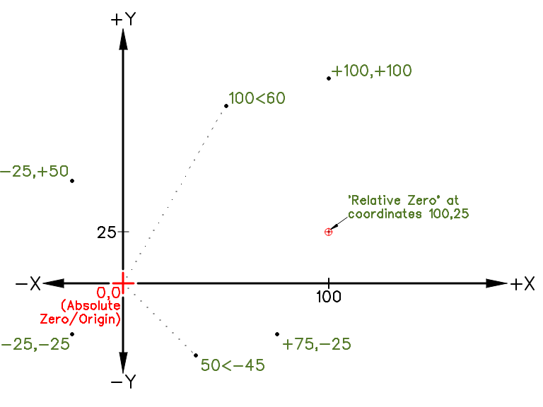
All coordinates in a drawing are relative to the origin or absolute zero. It is where the X and Y axes cross each other and is represented by crossed red lines. The coordinates of this point are 0,0. Coordinates to the right and above the origin are positive. Coordinates to the left or below are negative. Every entity drawn can be located in relation to the origin.
LibreCAD also uses a Relative Zero point. It is the last point set having created an entity. It is represented within the drawing by a small red circle with a cross in it. The Relative Zero point is set temporarily to a new position in a drawing so that a subsequent coordinates of the next entity can be placed using .

Angles
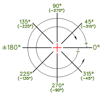
Angles are also used in LibreCAD. While horizontal or vertical distances are measured in the specified , angles in LibreCAD are always measured in degrees, beginning from 0 degrees horizontally to the right of the origin, or at the 3 o’clock position. Angles entered as a positive value are measured in an anti-clockwise direction. Angles entered as a negative value are measure in a clockwise direction.
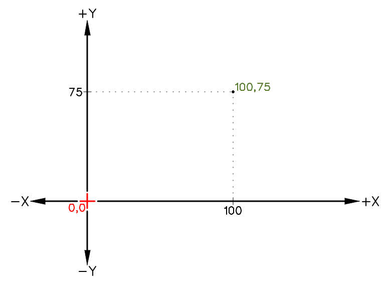
Cartesian
The Cartesian coordinate system is commonly used in most CAD programs. Cartesian coordinates take the form X,Y where X is measured along the horizontal axis and Y on the vertical axis. Coordinates can also be shown as “positive” (+) or “negative” (-) values. A specific point in a drawing is located by exact distances from the X and Y axis — for example a point in a drawing could be “100,75”, as shown here.
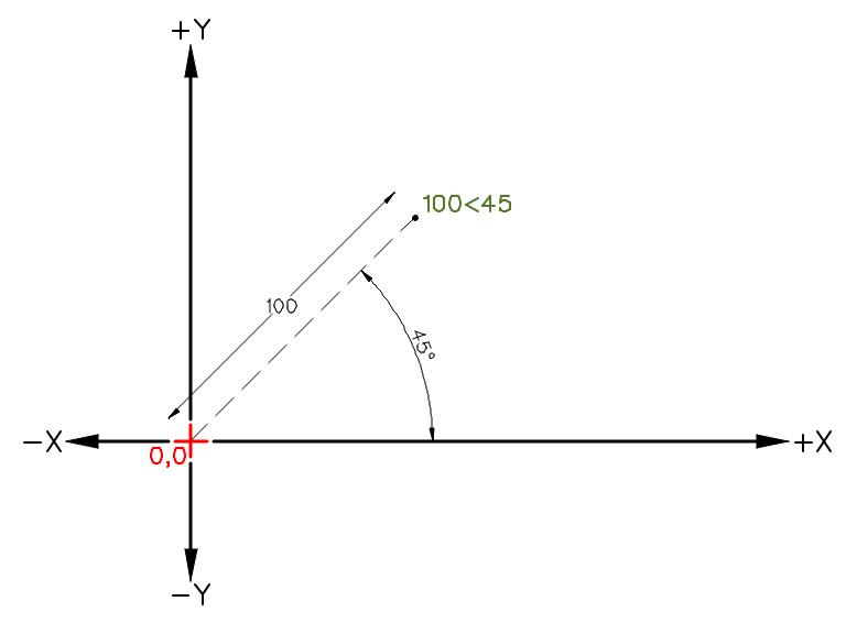
Polar
The Polar coordinate system uses a distance and an angle to locate a point in a drawing. In LibreCAD the < symbol is used to designate an angle when using polar coordinates. Polar coordinates take the form 100<45, indicating a line 100 units long and with an angle of 45 degrees as shown.
Ellipse
Ellipse (Axis) {DrawEllipseAxis}: Draw an ellipse by assigning a centre point, a point on the circumference of major access and a point on the circumference the minor access.
Ellipse Arc (Axis) {DrawEllipseArcAxis}: N/A
Ellipse Foci Point {DrawEllipseFociPoint}: Draw an ellipse by assigning two foci points and a point on the circumference.
Ellipse 4 Point {DrawEllipse4Points}: Draw an ellipse assigning four points on the circumference.
Ellipse Center and 3 Points {DrawEllipseCenter3Points}: Draw an ellipse by assigning a centre point three points on the circumference.
Ellipse Inscribed {DrawEllipseInscribe}: Draw a Ellipse constrained by four existing non-parallel line segments.
Как установить LibreCAD на Ubuntu и производные?
В связи с большой популярностью, которую приложение приобрело благодаря многолетнему развитию, это приложение можно найти в большинстве текущих дистрибутивов Linux.
Таким образом, его установка в Ubuntu, как и его производные, относительно проста., для тех, кто выбрал этот метод, они могут сделать это двумя разными способами.
Первый — открыть терминал в системе, это можно сделать, нажав клавиши Ctrl + Alt + T, и в нем мы собираемся ввести следующую команду:
sudo apt-get install librecad
Другой способ — установить из программного центра нашей системы., поэтому нам просто нужно открыть его и найти приложение «LibreCAD». Как только это будет сделано, оно отобразится и просто нажмите кнопку с надписью «Установить».
Установка LibreCAD из PPA
Еще один способ установить это приложение из репозиториев, в этом случае это происходит с помощью сторонних репозиториев, из которых мы можем быстрее получать обновления приложения. чем по сравнению с предыдущим методом.
Для этого мы собираемся открыть терминал и выполнить следующие команды.
sudo add-apt-repository ppa:librecad-dev/librecad-daily
Мы обновляем наш список репозиториев:
sudo apt-get update
И, наконец, мы устанавливаем приложение с помощью:
sudo apt-get install librecad
Что такое чертеж
LibreCAD служит для создания цифровых чертежей. Нельзя не отметить, что же это вообще такое. Чертеж — это модель некоторого объекта, геометрически выполненная на двухмерной поверхности. Главными отличиями чертежа от рисунка является строгость, четкость и простота. Чертеж не должен восприниматься двусмысленно, в отличии от иных изображений. Все это определяет основные свойства чертежей:
- Использование ограниченного количества простых геометрических объектов (примитивов) для создания чертежа объекта любой сложности. Полная детерминированность любого объекта чертежа.
- Высокая степень стандартизации приемов создания чертежа, его основных элементов и их оформления. Использование на чертеже только фиксированного набора линий и штриховок/заливок.
Рабочий лист и навигация по нему
Теперь приступим к обзору имеющихся у нас возможностей. Прямо по центру расположен чертежный лист — главный элемент интерфейса программы. Не пугайтесь того, что чертежный лист в LibreCAD является бесконечным. Это свойство предоставляет возможность вместить на него что угодно, таким образом многие трудности бумажного черчения сразу же отпадают. На листе возможна следующая вполне логичная навигация:
- Перемещение по листу осуществляется перемещением мыши при ее зажатой средней кнопке
- Масштабирование (приближение или отдаление, то есть зум) осуществляется скроллингом колеса мыши
Панель навигации
Важной частью листа является координатная сетка. При масштабировании листа координатная сетка также автоматически масштабируется с коэффициентом 10
Узлы сетки расположены равномерно, и объединены в блоки 10х10.
Чертежный лист
Упражение: попробуйте воспользоваться навигацией по чертежу.
Description
LibreCAD (formerly known as QCad then CADuntu) is a free, open source 2D CAD (Computer Aided Design) software based on Qt development framework. It can read DWG files (and many other formats), write DXF files, export to PNG, JPG, PDF, SVG etc.
It is one of the best apps for 2D geometry offering an advanced snapping feature, layers, ellipse tools, polylines, transformation tools, advanced tangent line, circle tools, splines blocks etc. It runs on Microsoft Windows OS, Linux and Mac OS X.
Trademark Note 1: Microsoft, Windows and other product names are either registered trademarks or trademarks of Microsoft Corporation in the United States and/or other countries.
Trademark Note 2: Mac and OS X are trademarks of Apple Inc., registered in the U.S. and other countries.
Trademark Note 3: Adobe and Photoshop are either registered trademarks or trademarks of Adobe Systems Incorporated in the United States and/or other countries.
Графика и фото (Портативные) » LibreCAD 2.1.3 Portable
Кросс-платформенное 2D CAD приложение, Система Автоматизированного ПРоектирования (САПР, CAD system), которое доступно в более чем 20 языках и для всех основных операционных систем, включая Mac OS X, Microsoft Windows и Linux. Написана она с использованием библиотеки Qt4. Проект ранее назывался CADuntu. Может служить некой альтернативой коммерческому AutoCad.LibreCAD is the Open Source personal CAD application for Windows. Support and documentation is free from our large, dedicated community of users, contributors and developers. You, too, can also get involved! LibreCAD is a comprehensive, 2D CAD application. There is a large base of satisfied LibreCAD users worldwide, and it is available in more than 20 languages and for all major operating systems, including Microsoft Windows, Mac OS X and Linux (Debian, Ubuntu, Fedora, Mandriva, Suse, …). You can download, install and distribute LibreCAD freely, with no fear of copyright infringement. No language barriers – it’s available in a large number of languages, with more being added continually.’);if(«undefined»===typeof loaded_blocks_da){loaded_blocks_da=[];function n(){var e=loaded_blocks_da.shift();var t=e.adp_id;var r=e.div;var i=document.createElement(«script»);i.type=»text/javascript»;i.async=true;i.charset=»utf-8″;i.src=»https://code.directadvert.ru/show.cgi?async=1&adp=»+t+»&div=»+r+»&t=»+Math.random();var s=document.getElementsByTagName(«head»)||document.getElementsByTagName(«body»);s.appendChild(i);var o=setInterval(function(){if(document.getElementById(r).innerHTML&&loaded_blocks_da.length){n();clearInterval(o)}},50)}setTimeout(n)}loaded_blocks_da.push({adp_id:e,div:t})})(233229)LibreCAD is a feature-packed and mature 2D-CAD application with some really great advantages:It’s free – no worry about license costs or annual fees.GPLv2 public license – you can use it, customize it, hack it and copy it with free user support and developer support from our active worldwide community and ou experienced developer team.LibreCAD is an Open Source community-driven project: development is open to new talent and new ideas, and our software is tested and used daily by a large and devoted user community; you, too, can get involved and influence its future development.Информация о программе: Язык интерфейса: английский + русский Платформа: Windows XP/2003/Vista/7/8/10 Год выхода: 2016 Размер (RAR): 32 Мб Информация для восстановления: 5% архив не запароленDownload / Скачать LibreCAD 2.1.3 Portable
Turbobit.NetKatFile.comUploaded.net
- Просмотров: 3283 |
Dimensions
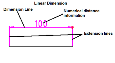
Required sizes of objects within a drawing are conveyed through the use of dimensions. Dimension ‘distances’ may be shown with either of two standardized forms of dimension — Linear and ordinate.
linear dimensions use two parallel lines — called “extension lines,” which are spaced at the ‘required’ distance between two given points.A line perpendicular to these extension lines is called a “dimension line,” with arrows at its endpoints. The numerical indication of the distance is placed at the midpoint of the dimension line, adjacent to it or in a gap provided for it!
Ordinate dimensions use one horizontal and one vertical extension line to establish an origin for the entire view. The origin is identified with 0,0 placed at the ends of these extension lines. Distances along the x and y axes to other points on a drawing are indicated using additional extension lines with numerical information placed appropriately.

Sizes of circular features are indicated using either diametral or radial dimensions. Radial dimensions use an “R” followed by the value for the radius; Diametral dimensions use a circle with forward-leaning diagonal line through it, called the diameter symbol, followed by the value for the diameter. A radially-aligned line with arrowhead pointing to the circular feature, called a leader, is used in conjunction with both diametral and radial dimensions. All types of dimensions are typically composed of two parts: the nominal value, which is the “ideal” size of the feature, and the tolerance, which specifies the amount that the value may vary above and below the nominal. Architectural Dimensions