Эмулятор электрических схем
Содержание:
- Frequently Asked Questions
- 2.10.2 DC Example 2: Variation of power dissipation with varying DC input voltage.
- 13.3 Small signal AC two port network simulation/analysis
- 13.4 Single tone large signal AC Harmonic Balance simulation
- 5.1 Fourier simulation
- Installation
- Every Circuit
- Интерфейс программы Multisim
- 3.1.2 Spice4qucs subcircuits with parameters
- Плюсы программы
- TINA-TI на русском
- Типы анализа
- Using manufacturers component data libraries
- 13.5 Multi-tone Large signal AC HB simulation
- Симулятор или эмулятор Arduino?
Frequently Asked Questions
-
How should I speak the word Qucs?
The correct pronunciation is kjuks.
-
What is the best way to get started with QucsStudio?
1) Watch the videos on this homepage.
2) Read the program help (F1 key) and the tutorial by Gunthard Kraus.
3) Test the example schematics from this homepage.
4) Modify the examples according to your needs.
5) Ask your remaining questions in the forum.
-
Why are there two different projects: Qucs and QucsStudio?
This situation isn’t nice indeed. But at some point it wasn’t possible
anymore to reach an agreement about future developments.
That’s why I left the Qucs project. After some time I went on programming
on my own and QucsStudio was born.
-
What are the differences between Qucs, Qucs-S and QucsStudio?Qucs is the original project,
which all others based on. The program is open-source and available for
Linux, Windows and MacOS. But it’s now rarely updated, so very few progress
can be expected only.Qucs-S is a Qucs fork.
It’s open-source and available for Linux and Windows. The graphical interface
supports the simulators
Qucs,
Ngspice,
XYCE and
SpiceOpus.
Again, updates are to be expected rarely.QucsStudio is a Qucs fork
that stems from the original project founder. It’s freely available for
Windows and not open-source. But it offers by far the most features
and is updated regularly.fREEDA is another open-source
simulator that uses the graphical user interface of Qucs. The last update
of this project was in November 2010.
-
How does the future of QucsStudio look like?
QucsStudio will continue to be freely available.
An open-source version is not planned.
-
Why does it take so long until a new version is released?
QucsStudio is a purely private project. Thus, there’s not much time
for the development. Unfortunately, support by users is very rare, too.
Any help will speed up the progress!
-
I don’t want all the data to be saved in .qucs\ in the
user directory. How can I change this?
The wanted directory can be set with a minus sign in the command line,
e.g. running qucs.exe -«C:/projects».
A file link is the best way to
realize this. I.e. drag’n’drop qucs.exe onto the desktop
by pressing the Alt key. Then click with the right-hand mouse button
onto this icon and choose Properties in the opening menu.
In the appearing dialog the command line can be entered.
Having this done, QucsStudio can be started with the new directory
by double-clicking on this link.
-
Does QucsStudio run on other operating systems than Windows?
With the software Wine,
Windows applications like QucsStudio runs on Linux, MacOS and BSD.
This was successfully tested many times.
If simulations with microstrip components end up with an error message
(about sinh function), the wrong DLLs are used. Then, start winecfg.
In the Library tab add msvcp100 and msvcr100 and set them
to native.
-
What should I do if my question isn’t answered here?
Please have a look into the forum.
A lot of topics have already been discussed there.
And of course, you can also ask your own questions.
2.10.2 DC Example 2: Variation of power dissipation with varying DC input voltage.
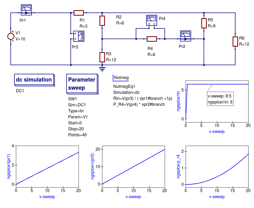
Figure 2.12 DC example 1 with varying DC input voltage: demonstrating the use of a DC sweep simulation.
- Draw the circuit diagram shown in Figure 2.11,
- Select simulator Ngspice,
- Add the dc simulation, Parameter sweep and Nutmeg component icons to the drawn schematic,
- Complete the Parameter sweep and Nutmeg component data entries so that they are the same as given in Figure 2.11,
- Press the F2 to simulate the circuit,
- Plot the graphs illustrated in Figure 2.11,
- Check that your results are the same — if not or the simulation fails check your schematic for errors and re-simulate.
Notes:
- Current probe values are represented by the SPICE 3f5 notation: vpr1#branch and vpr2#branch.
- There is a discontinuity in Rin when the vpr1#branch current is zero Amperes; hence the need for the dummy 1pA in the Nutmeg equation for Rin.
13.3 Small signal AC two port network simulation/analysis
The spice4qucs extensions introduce post-simulation data conversion for two-port networks centred
around Qucs-S Nutmeg scripts and Qucs-S Nutmeg equation blocks. These are designed specifically to
work with Ngspice and Xyce. Conversion of two port parameters from
one format to another format is simply one example of the application of Qucs-S embedded nutmeg scripts for the
control of circuit simulation and the extraction of circuit parameters from output data.
The Xyce circuit simulator is more limited in that it does not have a post-processing scripting language
for extracting transfer function parameters and other data from simulation output. However, it
does allow SPICE style AC .PRINT statements which can include equations provided these are
written in a form constructed from the real and imaginary components of circuit voltages and
currents. In practice this is not very convenient, particularly when these equations involve many
algebraic terms. At this time the Xyce facilities for the extraction of AC data items are at a rudimentary stage in the
packages development and for this reason are not considered further in this document.
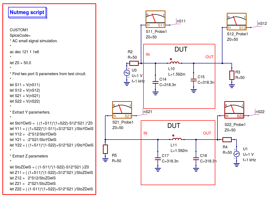
Figure 13.3 Nutmeg script controlled simulation and two-port parameter extraction.
Figure 13.3 presents an S-parameter test bench used to extract the S parameters of the same low pass filter
introduced in Figure 13.1. However, unlike Figure 13.1 Qucs/Qucs-S simulation icons are NOT attached to the
test-bench circuit schematic. Instead a Qucs-S Nutmeg script is used. This script controls the simulation sequence
and provides post processing algebraic equations which generate small signal AC \(Y\) and \(Z\) parameters from the data
output by the S-parameter probes. Figure 13.4 shows a set of simulation plots obtained with the Nutmeg script and SPICE OPUS. Identical
data was recorded with Ngspice. However, one difference was noticed when simulating circuits via the Nutmeg script route. SPICE OPUS
requires that the code words, like for example ac and let, must be entered with lower case letters, otherwise the SPICE OPUS simulation fails.
Chapter 8 presents much more detail on how to set up Nutmeg scripts and gives a number of additional examples of their use in Qucs-S circuit
simulation.

Figure 13.4 Typical S-parameter, \(Y\) parameter and \(Z\) parameter data for the test circuit given in Figure 13.3.
One of the pioneering circuit simulation features implemented by Qucs is the Equation block. This allows blocks of algebraic equations to be attached
to a circuit schematic. Any equations which do NOT include quantities computed during simulation, like circuit voltages and currents, are evaluated prior to the start of simulation.
These quantities remain fixed during simulation and may be referenced by the simulator when calculating voltages and currents. In contrast, if an Equation block includes
variables which are functions of simulation variables these are evaluated, based on the stored simulation output data, after a simulation finishes.
Qucs has a Octave style numerical analysis package built into the software for this purpose.
Qucs-S uses a slightly different approach to post simulation data processing. Both Ngspice and Xyce use an extended form of the SPICE nutmeg software for post-simulation data processing.
Unfortunately, because Xyce does not include a feature equivalent to SPICE nutmeg, AC post-simulation data processing is not possible with Xyce.
To setup and use a Qucs-S Nutmeg equation block place the Nutmeg icon on an empty schematic sheet and enter the individual variable equations in a
similar fashion to Qucs Equation blocks. Once complete copy the Nutmeg equation black to the current work circuit schematic.
Such Nutmeg equation blocks are called Templates by the Qucs-S Development Team. These templates can be saved in a project and used over and over again.
Templates add a new and important facility to Qucs-S which allows users to develop libraries of-post simulation data processing scripts and store them for future use.
See Chapters 7 and 8 for more details and examples of the use of Qucs-S Custom Simulation technology and Nutmeg equation blocks.
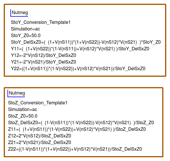
Figure 13.5 shows Qucs-S Templates for the conversion of S-parameters to \(Y\) and \(Z\) two port parameters. Note that these do NOT include commands for
simulations, for example ac ……, and do not have the same named variable defined more than ONCE.
13.4 Single tone large signal AC Harmonic Balance simulation
The Spice4qucs subsystem supports Xyce single tone and multi-tone Harmonic Balance (HB).
Unlike the rudimentary version of HB simulation implemented in Qucs the Xyce version can simulate circuits
with a full range of SPICE components. It is also faster and much more stable. In general no changes to the SPICE
semiconductor device or component models are required. To invoke single tone HB just place
the Qucs-S icon on a circuit schematic, define the number of harmonics and
simulate the circuit with Xyce. The spice4qucs output data parser automatically converts output variable names to Qucs notation.
For example, for node voltage plot .
Figure 13.6 shows the schematic and Figure 13.7 the simulation output plots for a basic diode circuit similar to the original Qucs HB example found
on the Qucs web site. For comparison Figure 13.7 presents the output voltage spectrum plots generated by Qucs and Qucs-S/Xyce.
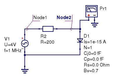
Figure 13.6 Diode clipper harmonic balance simulation.
The HB simulation results for the diode clipper circuit are shown in the Figure 13.7.
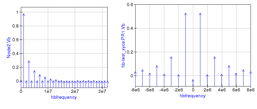
Figure 13.7 Output voltage spectrum at Node2 for Qucs (left plot), and measured with voltage probe Pr1 for Xyce (right plot).
Comparing these two plots highlights an obvious difference in the plot frequency scales.
The Qucs-S/Xyce output plot is represented as a function of negative and positive frequency components.
In this example there are eight harmonics () arranged as 8 positive frequencies and eight
negative frequencies plus a DC component.
Qucs HB simulation data are output as a plot of frequency domain spectral amplitude components \(|H|\), where
\
\(U(0)\) is the DC spectral component, \(U(f_n)\) is the magnitude of a harmonic component at frequency \(f_n\) and \(n=1, 2, 3, 4,…\).
In contrast to Qucs, Xyce outputs HB voltage and current simulation data as plots of complex conjugate spectral components, where
\
5.1 Fourier simulation
The Qucs-S implementation of Fourier simulation allows users to perform a Fourier analysis of
one or more time domain circuit signals and to investigate their spectrum in the frequency domain.
Qucs-S Fourier simulation is implemented by Ngspice, Xyce and SPICE OPUS.
Fourier simulation is available to Qucs-S users via a special icon called Fourier simulation.
This icon is located in the simulations group. To request a Fourier simulation
place a copy of the “Fourier simulation” icon on the current work schematic alongside a transient simulation icon.
Qucs-S Fourier simulation uses the simulation data generated by a transient simulation and has no meaning without a set of transient
time domain data. The link between Fourier simulation and transient simulation is formed by entering the
name of the coupled transient simulation as the first property of Fourier simulation.
The Fourier analysis property list has the following entries:
- — Linked transient simulation icon name.
- — Number of harmonics: variable number for ngspice and SPICE OPUS but fixed at 10 for Xyce.
- — This parameter is the fundamental frequency of the generated frequency domain spectrum.
- — This parameter is a list of output signals. These may be node voltages and currents. In the list each entry must be space separated.
Fourier simulation creates four output vectors for each specified output signal, for
example in the case of signal :
- — Magnitude spectrum.
- — Phase spectrum (in degrees–).
- — Normalized magnitude spectrum.
- — Normalized phase spectrum.
Qucs-S allows each of these four display vectors to be plotted.
Here is a small example of a Fourier simulation which demonstrates the main features introduced above
and the relation between small signal AC simulation and Fourier simulation.
Installation
Linux
Debian repository
Go to download
repository
- Download GPG key:
wget -c
http://download.opensuse.org/repositories/home:/ra3xdh/Debian_9.0/Release.key - Add the following line to /etc/apt/sources.list:
deb http://download.opensuse.org/repositories/home:/ra3xdh/Debian_9.0/ ./ - Import key and update repos:
apt-key add Release.key
apt-get update - Install Qucs-S
apt-get install qucs-s
*.debdpkg
dpkg -i qucs-s-0.0.19S_amd64.deb
You may need to install the following dependencies: lib4qt4-qt3support,
ibqt4-svg, ngspice
RPM packages for CentOS and Fedora
You need to simple add reposotries using the yum package manager. Let’s consider
example for CentOS:
- First add repository
yum-config-manager --add-repo http://download.opensuse.org/repositories/home:/ra3xdh/CentOS_7/
yum-config-manager --enable ra3xdh - Then check that repository is added
yum repolist alll
-
And finally install the qucs-s package
yum install qucs-s
Building from source
- Install all necessary dependencies: Qt, C++ compilers, etc.
- Install desired simulation backends: Ngspice, XYCE, SpiceOpus. You can use all
these backends together or only one of them. Install basic Qucs (0.0.18 or
newer) if Qucsator is needed. - Download and unpack tarball
- Use CMake to compile. Autotools doesn’t support this installation mode and
will not work! - Invoke make and make install
tar xvfz qucs-s-0.0.21.tar.gz
cd qucs-s-0.0.21
mkdir builddir
cd builddir
cmake ..
make
make install
The last command make install should be executed from root user. It will
install Qucs-S into default prefix /usr/local/. Use -DCMAKE_INSTALL_PREFIX=...
to override the default locationNo additional configure options are needed now.
Slackware SlackBuild
- Clone this repository:
git clone https://github.com/ra3xdh/QucsS.SlackBuild - Run SlackBuild as root:
cd QucsS.S.SlackBuild
./qucs-S.SlackBuild - Install txz package with installpkg command
Windows
http://ngspice.org/https://xyce.sandia.gov
Important note for Ngspice on Windows: Unpack Ngspice ZIP package strictly to the
C:\SPICE location. Otherwise XSPICE model will not work! If you are getting strange errors with Ngspice
on Windows and cannot ot simulate even simple circuit, please check that Ngspice is installed strictly in
C:\SPICE . All Ngspice packages including offcial should be installed in a such way.
It’s recommended special build of Ngspice-26 for Windows
Ngspice26_QucsS.zip
. Default Ngspice package also will work but it may have some limitation. Custom
Ngspice build solves the following issues:
- Windows GUI of Ngspice is disabled. It allows Qucs-S to obtain logs from
Ngspice. - Added CMPP preprocessor and C headers set mandatory for development of
CodeModel libraries. Default Ngspice build is shipped without it.
Every Circuit
Поддерживает всё что мне нужно, может я и не самый лучший радиоинженер, но вот радиоэлемента увлекаюсь еще в ого. Qucs полезная программа.
И именно тут я смог Qucs скачать на русском языке!
OrCAD Самая популярная программа компании Cadence, содержащая полную среду для коммерческих проектов PCB, содержит все компоненты, необходимые для проектирования печатных плат, такие как: модуль для введения схем; редактор печатных плат с интегрированным управлением проектирования. Ответить Ответить с цитатой Цитировать Татьяна
Времени и трудозатрат по определению меньше. В данном обзоре рассмотрим 3 самых популярных симулятора электрических цепей для Андроид устройств, сравним их возможности, потенциал и удобство использования.
Интерфейс программы Multisim
Начнем с изучения интерфейса программы.
Основные функциональные панели программы показаны на следующем рисунке.

Отдельный интерес представляет панель компонентов. С помощью панели компонентов осуществляется доступ к базе компонентов. При нажатии на любую из выбранных пиктограмм компонентов схем открывается окно Выбор компонента. В левой части окна осуществляется выбор необходимого компонента.

Вся база данных компонентов разделена на разделы (пассивные элементы, диоды, транзисторы, микросхемы и т. д.), а разделы на семейства (например, для диодов – это сами диоды, стабилитроны, светодиоды, тиристоры и т. д.). Надеюсь идея понятна.

Так же в окне выбора компонента можно посмотреть обозначение выбранного компонента, описание его функции, выбрать тип корпуса.
3.1.2 Spice4qucs subcircuits with parameters
Subcircuits which have component or physical parameter values set by a list of names and values attached to a schematic symbol add a significant “value added”
feature to the subcircuit concept. This form of subcircuit can, for example, be used to represent manufacturers product variations which have identical circuits but
require component values or device parameter values of differing value. Unfortunately, SPICE 3f5 only implements subcircuits without parameters.
Recent generations of open-source GPL circuit simulators, including Ngspice, Xyce and SPICE OPUS, have been extended by their Development Teams to allow subcircuits with parameters.
One consequence of this is that over time divergence of the SPICE subcircuit statement syntax has occurred amongst different circuit simulators.
implements a common subset of the published extended SPICE subcircuit syntax. This works well, but does have one disadvantage however, in that some published subcircuit netlists may require a small amount of editing before they will simulate with . One code word often found in the SPICE extended subcircuit syntax is the term PARAMS:. This can occur in an X subcircuit call to
signify a subcircuit with parameters. As this is optional in Ngspice, and indeed in other SPICE derived circuit simulators, it is not implemented in .
Qucsator, Ngspice, Xyce and SPICEOPUS all allow parameters to be attached to subcircuit symbols and to be used in design equation calculations.
As an introductory example Figure 3.6 illustrates a circuit schematic and user generated symbol for a simple Qucs harmonic generator composed of a fundamental AC signal and three sinusoidal harmonic components. Parameters \(f1\) to \(f4\) set the frequencies of the harmonics. The Qucs Equation block, at the subcircuit internal circuit level, is used to calculate the individual harmonic frequencies. In a similar fashion \(ph1\) to \(ph4\) represent the phases of the signal harmonics.
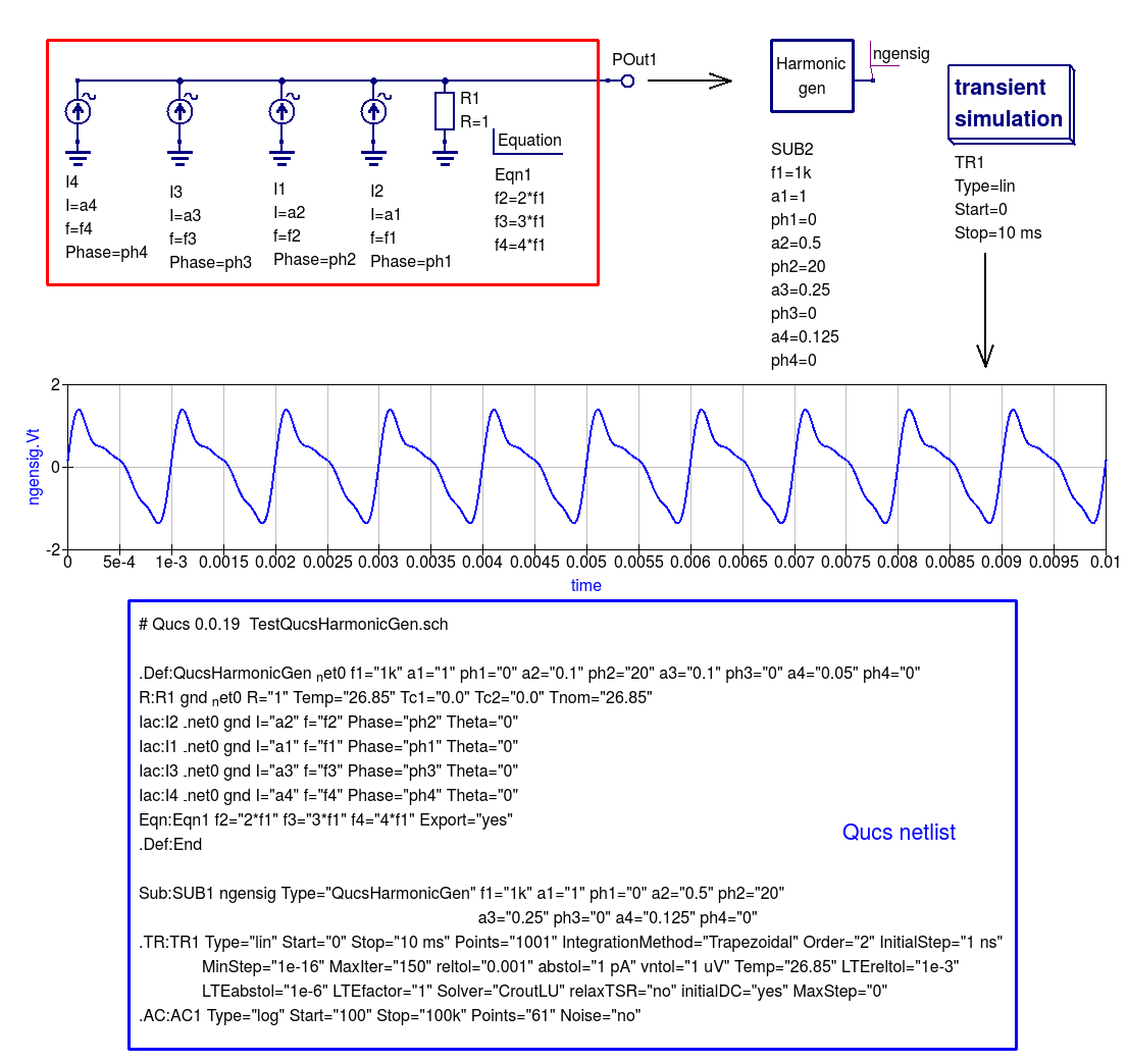
Figure 3.6 Qucs subcircuit sinusoidal harmonic signal generator: \(f1\) is the fundamental frequency and \(f2\) to \(f4\) the higher order harmonics;
\(ph1\) to \(ph4\) the phases of the fundamental signal and its harmonics. For clarity long Qucs netlist lines have been spread over more than one line.
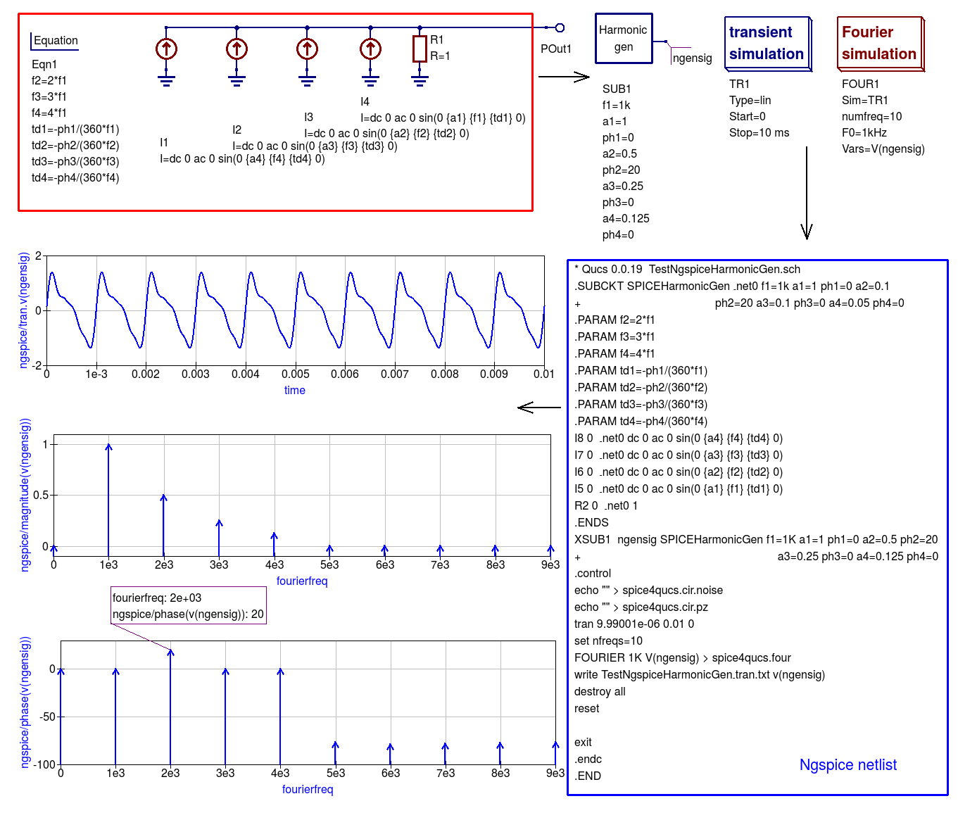
Figure 3.7 Ngspice subcircuit sinusoidal harmonic signal generator.
Figure 3.7 shows an Ngspice version of the Qucs sinusoidal harmonic generator illustrated in Figure 3.6. A casual look at these two subcircuit diagrams shows that they are not dissimilar.
However, there are a number of subtle changes apparent from the diagrams. First it is important to realise that the Qucs and SPICE sinusoidal (sin) signal generator specifications are different;
Qucs requires the signal phase and SPICE the signal delay to be specified as parameters. In Figure 3.7 extra equations to convert phase to time delay are added to Equation block Eqn1 inside subcircuit SPICEHarmonicGen.
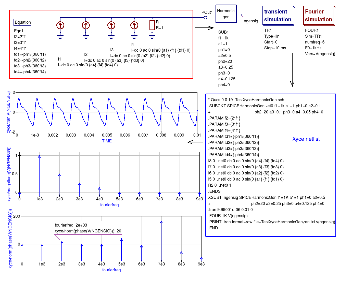
To ensure that Eqn1 variables, for example frequency \(f2\), are passed to the subcircuit component values as numerical values SPICE curly deliminator brackets, {…}, are placed round equation variable names. Finally, it is important to realize that the order of the variables in Equation blocks are important. Qucs allows them to be in any order because it arranges all entries into a sequence which ensures each variable can be allocated a numerical value before it is used in other equations. However, SPICE does not do the same but assumes
that all variables included in the right hand side of an equation have been allocated a numerical value prior to being used in the calculation of the variable named on the left hand side of the same equation.
To check that the Ngspice generated waveform is correctly generated a Fourier analysis of signal \(V(ngensig)\) is displayed on Figure 3.7. At frequencies above \(f4\) the phase values have no meaning.
The simulated signal waveform obtained with SPICE OPUS was found to be similar to that obtained with NGSPICE, see Figue 3.8. Try simulating the sinusoidal harmonic generator waveform with SPICE OPUS to check this statement for your self.
Плюсы программы
- Общайтесь большими группами. Организуйте бесплатные конференции в Zoom до 100 участников.
- Нет времени регистрироваться? Подключайтесь к конференции без регистрации в программе.
- Общайтесь за пределами офиса! Пользуйтесь функциональным мобильным приложением Zoom Cloud Meetings.
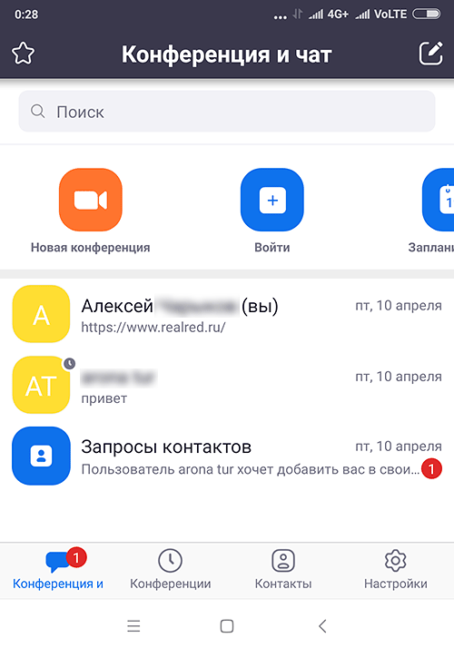
- Не успели скачать Zoom на компьютер? Присоединяйтесь к общению через ссылку-приглашение в браузере.
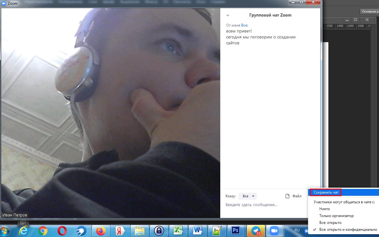
- Информация не пропадет. Сохраняйте историю переписки в чате.
- Вы не забудете, что обсуждали. Загружайте аудио и видеозапись конференции на компьютер.
- Экономьте время. Планируйте конференции в календаре Google через дополнение браузера Zoom Scheduler.
- Хотите продублировать голос текстом? Добавляйте и сохраняйте субтитры.
- Надоело писать одинаковые ответы? Настройте автоответы в чате.
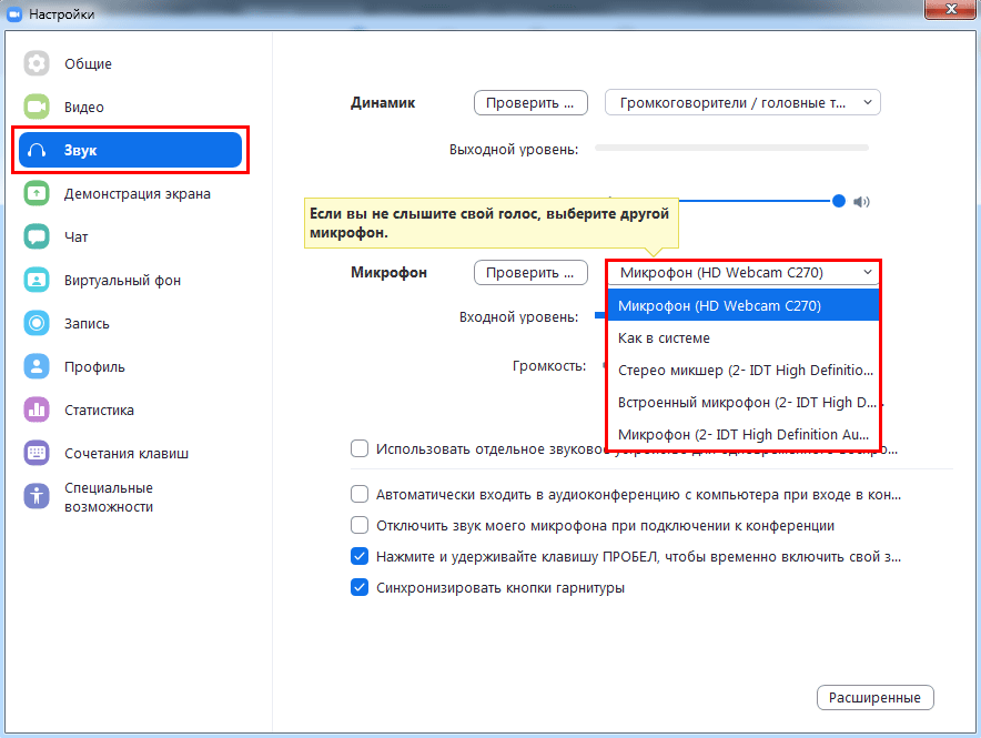
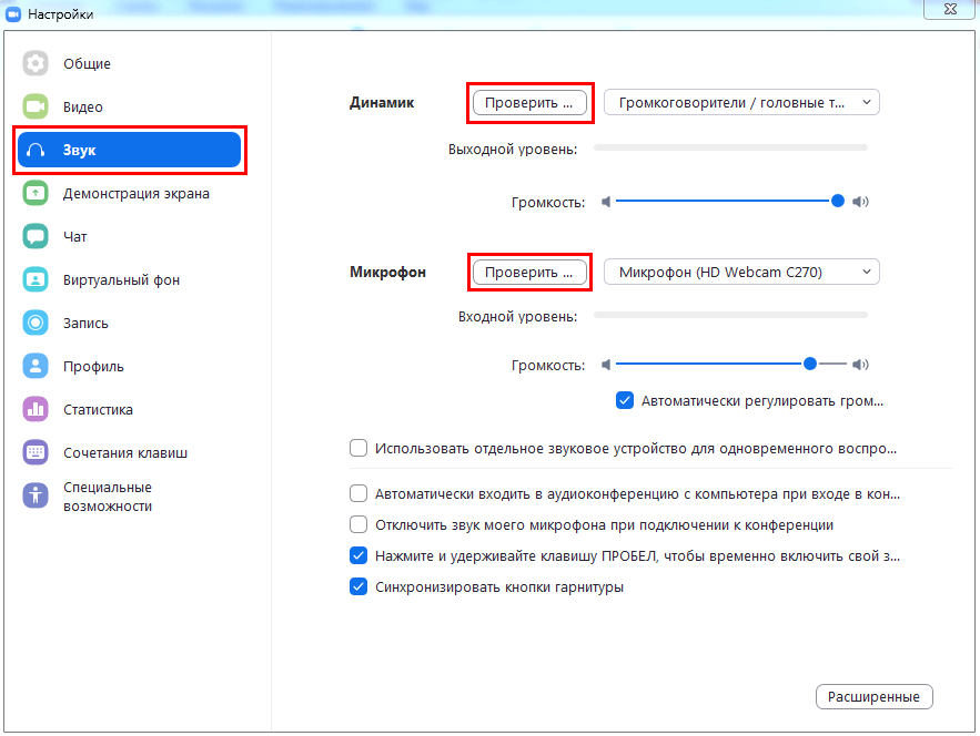
- Выбирайте оборудование. Используйте встроенные в ноутбук микрофон и динамик или внешнюю гарнитуру.
- Пускайте только избранных. Активируйте зал ожидания и подтверждайте право участников присоединиться к конференции.
- Держите организатора в курсе. Настройте уведомления по E-mail, когда участники раньше организатора вошли в конференцию.
- Информируйте об отмене. Уведомляйте участников по электронной почте в случае отмены конференции.
- Оборудование не подведет. Проверяйте работу микрофона и динамика перед началом конференции.
- Открыто много программ одновременно? Работайте в приложении Zoom на двух мониторах.
- Оперативно рассылайте приглашения в мессенджерах. Включите автоматическое копирование в буфер URL приглашения после начала конференции.
- Не пропускайте выступления! Настройте уведомление о скором начале конференции.
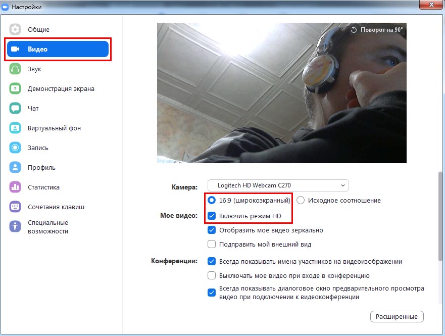
- Транслируйте видеопоток в высоком качестве. Настройте широкоформатный режим трансляции видео в HD.
- Отслеживайте докладчика. Подсвечивайте имена участников на видеоизображении.
- Настройте чат под себя. Выберите темный или светлый цвет боковой панели чата. Установите режим отображения непрочитанных сообщений и уведомлений.
- Позаботьтесь о приватности. Блокируйте нежелательных пользователей чата.
- Оберегайте покой докладчика. Отключите звук уведомлений во время вызовов и конференций.
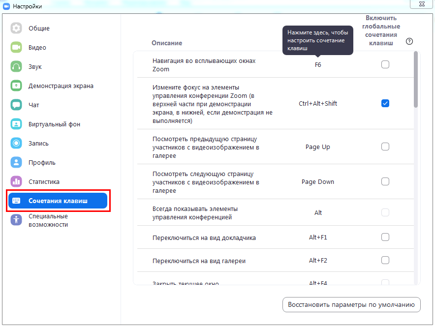
- Повышайте удобство! Настройте горячие клавиши, чтобы упростить работу с программой.
TINA-TI на русском

SPICE-симулятор для серьезных разработок, имитации работы и отладки схем для продвинутых радиолюбителей.
Программа позиционируется как SPICE-симулятор с доброжелательным и доступным интерфейсом, не требующим значительных усилий для усвоения навыков работы по проектированию и симуляции электронных устройств. Количество устройств и узлов неограниченно, подходит для масштабных проектов, фишка программы – конструирование аналоговых схем и импульсных источников питания.
В симуляторе 6 категорий устройств: базовые пассивные радиодетали, ключи, полупроводники, измерительные приборы, макромодели сложных устройств и источники. Несколько схем включены в комплект в качестве примеров.
TINA-TI предоставляет хорошие возможности симуляции и анализа. Разработки перед апробированием проверяются на ошибки (ERC) и выводится перечень найденных ошибок схемы. Ошибки выделяются маркерами.
Конструктор работает в английской и русскоязычной версиях.
Типы анализа
Для радиолюбителей и самодельщиков есть всё в этом китайском магазине.
ПО платное, но есть бесплатная дневная ознакомительная версия. Circuit Sims : Это был один из первых вебов исходя из эмуляторов электроцепи с открытым кодом я тестировал несколько лет назад. Программа работает, начиная от Windows 98 и заканчивая Windows 7.
Можно заключить, что несмотря на свои недостатки Qucs представляет собой весьма достойную альтернативу проприетарным САПР для моделирования электронных схем.
Дополнительно данный софт имеет в своем составе множество показательных образцов. Система является достаточно стабильной и надежной, легка в освоении и работе. Некоторые из приложений платные, но у них есть демо версии с которыми можно подробно ознакомиться.
Файлы также можно экспортировать во многие форматы, включая JSON. Все полученные условными приборами информационные данные сохраняются в памяти компьютера. Программа имеет возможность создавать: разнообразные инженерные и технические рисунки; электронные схемы; составлять эффектные презентации; разрабатывать организационные схемы, маркетинговые и многие другие. Давайте перенесем щупы к лампочке и поставим измерение постоянного напряжения с пределом 20 Вольт.
Особенности симулятора электрических схем Qucs
По желанию производитель предлагает относительно недорогую конструкцию печатной платы в соответствии с созданной конструкцией. Я представляю, на сколько облегчают труд подобные программы. Существует множество бесплатных версий. Ведётся разработка системы синтеза активных фильтров для Qucs ожидается в версии 0.
Отличная анимация движения и импульсов токов, а также зарядки и разрядки конденсаторов. Я представляю, на сколько облегчают труд подобные программы. Более подробную информацию о программе вы можете найти на нашем сайте. Для управления сложными схемами включена возможность разворачивания подсхем и формирования блоков. Эх, раньше бы создали эту прогу Ответить Ответить с цитатой Цитировать владимир
Бесплатная версия программы не позволяет создавать электронные схемы в коммерческих целях. Суммарное напряжение последовательно соединенных батареек 3 вольта. Circuit Sims 2. Это измерительные щупы. Программное обеспечение Quite Universal Circuit Simulator является редактором с графическим интерфейсом с комплексом технических возможностей для конструирования схем.
Как работает транзистор? Режим ТТЛ логика / Усиление. Анимационный обучающий 2d ролик. / Урок 1
Using manufacturers component data libraries
Electronic components manufacturers often provide spice models of components in
datasheets. You can attach these datasheet spice models using SPICE netlist
component. You need to perform the following steps to use Spice-model from
component datasheet. Spice netlist builder substitutes SPICE-models directly to
output netlist without any conversions.
1. Extract Spice netlist text and save it as text file. You can use any
extension for this file. Preferable are .ckt , .cir, .sp
2. Place on schematic component SPICE netlist and attach SPICE netlist nodes
to component port using standard SPICE component properties dialog.
- Simulate schematic with Ngspice/Xyce.
It’s need to note that SPICE-netlist of component must not be ended by
directive. In this case simulator exits after it reads
routine and simulation cannot be executed.
The example of spice model usage (LM358 opamp) is shown in the Figure 3.12
Figure 3.12 AC Simulation of LM358 opamp with Ngspice.
Here is the netlist of LM358 spice-model. Model can be found in LM358
datasheet.
13.5 Multi-tone Large signal AC HB simulation
Since Xyce release 6.3 the package has supported multi-tone HB simulation. Xyce multi-tone allows more
than one tone frequency in the properties box.
Perform the following steps to setup a multi-tone Xyce HB simulation:
- Specify a list of space separated frequencies in the parameter box.
- Specify a comma separated list of the number of harmonic frequencies for each of the source signals in the parameter box.
- Construct an input signal generator using two or more series AC voltage sources, with the required frequencies and amplitudes, or
- construct an input signal generator using two or more parallel AC current sources driving a one Ohm resistor.
Normally, multi-tone HB simulation signal sources consist of two or three AC sources with different frequencies and similar amplitudes.
With two AC signal sources with nearly equal frequencies, that are not integer related, circuit modulation components can be extracted from circuit output spectra.
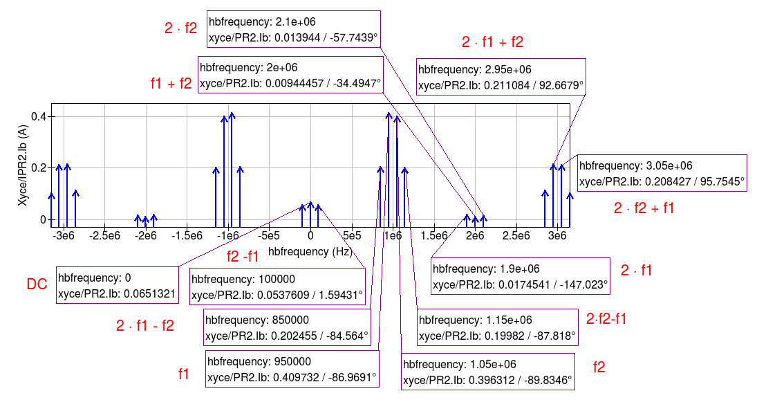
A multi-tone HB example illustrating this feature is given in Figure 13.8, where two AC signals of 0.8 V peak and frequencies 0.95 MHz and 1.05 MHz are applied to a simple diode circuit.
The frequencies of individual diode current spectral components are show as combinations of signal frequencies \(f_1\) and \(f_2\) and marked in red on Figure 13.9.
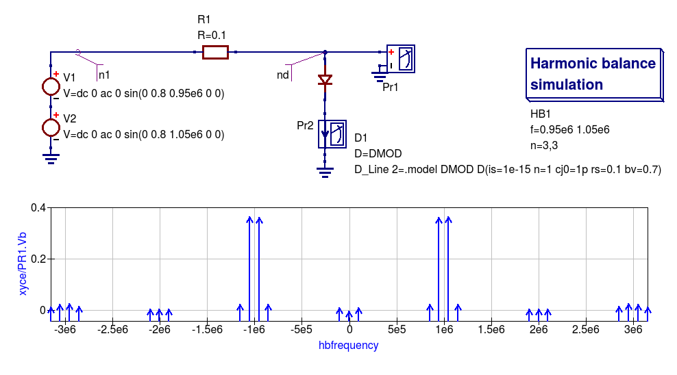
Figure 13.8 An example diode 2-tone Xyce HB simulation circuit plus diode voltage spectra.
Симулятор или эмулятор Arduino?
Давайте сразу договоримся, что в статье мы будем использовать оба этих термина, хотя их значение вовсе не идентично. Симулятором называют устройство или сервис, имитирующие определенные функции другой системы, но не претендующим на создание точной копии. Это некоторая виртуальная среда, в которой мы просто моделируем другую систему. Эмулятор – это полноценный аналог, способный заменить оригинал. Например, Tinkercad симулирует работу электронных схем и контроллера, но при этом он является эмулятором ардуино, реализуя практически все базовые функции Arduino IDE – от среды редактирования и компилятора до монитора порта и подключения библиотек.
С помощью этого класса программ можно не только рисовать электронные схемы, но и виртуально подключать их к электрической цепи с помощью встроенного симулятора. В режиме реального времени можно наблюдать за поведением схемы, проверять и отлаживать ее работоспособность. Если в такой симулятор добавить виртуальнyю плату Arduino, то можно отследить поведение схемы и в ардуино-проектах. Для отладки скетчей во многих известных сервисах присутствует также возможность загрузки настоящих скетчей, которые “загружаются” в модель и заставляют вести схему с подключенными элементами так же, как и со включенной реальной платой. Таким образом, мы сможем эмулировать работу достаточно сложных проектов без физического подключения Arduino, что существенно ускоряет разработку.