Создание схемы в fritzing
Содержание:
- Release version 0.9.3b
- The PCB View
- No need of Hardware to design a circuit with Fritzing:
- Start here to learn all about of Fritzing software tool
- Скачать Fritzing
- Our Publications
- Начало работы в Fritzing
- Free electronic design automation software
- Hand-routing
- Создаем SVG-файл макета компонента
- Commercial Tools
- Auto-routing
- Videos
Release version 0.9.3b
Continuously updated parts library
The Fritzing parts library is now stored online at github and is automatically checked
for updates. This means you will now get new parts (or fixes) in the moment when they are created.
No need to wait for the next Fritzing release anymore!
Critical bug fix for messed up PCB traces
We have been plagued by an annoying bug that occasionally caused PCB traces to get loose and flip around.
It has been tricky to track down but it’s finally fixed, sigh.. Plus, the fix will recover any files that
have been mangled by this bug!
High-DPI display support
Fritzing now looks properly on High-DPI (aka Retina) displays on all platforms.
It’s not really high-res but scaling well according to the higher screen resolution.
Easier handling of self-created parts
Custom / self-made parts and bins used to be stored in a hidden location on your hard
drive, which made it really annoying to edit them with an external tool such as Illustrator
or a text editor.
They are now conveniently located in your ~/Documents/Fritzing folder for easy access!
Load/Save uncompressed fritzing files (.fz)
You can now alternatively save your fritzing sketches as an uncompressed set of files (.fz
plus additional custom parts etc). This allows for proper versioning with systems like git or svn.
Thanks to Sergio Oller (zeehio) for this contribution.
File icons
fzz, fzb, fzp, etc. now also have shiny file icons on Mac (thanks to scribblemaniac)
and Ubuntu Linux (thanks to el-j — for the latter you have to run the install-fritzing.sh script)
New Parts
Added and/or revised by Fabian Althaus (el-j):
- Full set of Molex Picoblade and Hirose DF13 header series, thanks to steelgoose
- Lots of new SparkFun parts, thanks to support from SparkFun:
- ESP8266 Thing Dev Board
- Stepoko
- Arduino Pro Mini 3.3V and 5V
- Arduino Mega Pro 3.3V
- Badger RedStick and Array
- Myoware Cable Shield, Power Shield, and Proto Shield
- Ludus Protoshield and Protoshield Wireless
- CAN-Bus Shield
- MIDI Shield
- FemtoBuck LED Driver
- Load Sensor Combinator
- Soil Moisture Sensor
- BME280 Breakout
- LSM303C 6-DOF-IMU Breakout
- SHT1x Humidity/Temperature Breakout
- 16 Output I/O Expander Breakout — SX1509
- Raspberry Pi 3 and Zero, thanks to Nagaranudit
- DQuid IO GPRS, thanks to DQuid team
- nRF24L01 2.4GHz RF, thanks to Doume
- nRF24L01+ 2.4GHz RF, thanks to Richard Bruneau
- RFduino BLE SMT, thanks to Arnaud Boudou, Felix Kosmalla
- , thanks to Mike Causer
- Pololu A4988 stepper motor driver, thanks to Matteo Perini
- WeMos D1 Mini, thanks to Mike Causer
- Adafruit HUZZAH ESP8266 Breakout, thanks to pkurtans
- Adafruit push-power button
- Adafruit Powerboost 500C, thanks to Dean Cording
- Bluetooth HC-05 module, thanks to Computação na Escola
- HC-SR04 distance sensor, thanks to Ricky Ng-Adam
- SIM800L GPRS breakout, thanks to AlbMA
- Monacor LTR 110 line transformer
- MBR745 Schottky diode, thanks to S. van Doorn
- 10A rectifier diode, thanks to tomaskovacik
- OMRON G5LE and NVF4-2 relays, thanks to tomaskovacik
- MPX2010 pressure sensor, thanks to Knutse
- MPX4250AP pressure sensor, thanks to Old Grey
- 174917 DENSO ECU-socket, thanks to Old Grey
- Rotary Switch 12 position 1 pole, thanks to Old Grey
- 4060 counter/divider, thanks to neutmute
- LM124-324 Quad Opamp, thanks to Knutse
- Hi-Link HLK-PM01 power module, thanks to inahas
- LTC3105 step-up DC/DC converter
- Refined ruler design, thanks to duff2013
New/updated Translations
- Czech, thanks to Vasekdvor
- German, thanks to Atalanttore and aknoerig
- Italian, thanks to Gianpaolo Macario
- Polish, thanks to jacekjaros
- Portuguese, thanks to Bruno Ramalhete
- Spanish, thanks to bazza
- Turkish, thanks to Kaan Özdinçer
- Vietnamese, thanks to Duyệt Đinh Xuân
..and various smaller improvements and fixes, including contributions from Duane Johnson,
Luke Benstead, Nicolas Raynaud, scribblemaniac and duff2013. Thanks!
The PCB View
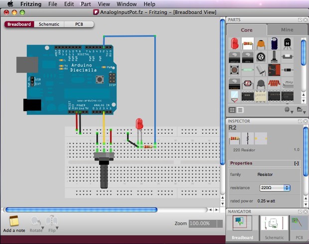
So your circuit works and also looks great in Fritzing’s Breadboard View.
Let’s now have a look at the PCB View. To switch to the PCB View use the Navigator or the View Switcher. While it is very easy to recognize parts in the Breadboard View, the PCB View might look a bit confusing at first glance. The reason for this is that the PCB View only shows the necessary information needed for the PCB design. This information is shown in different layers. To view or hide layers, use the View options in the menu bar. Learn more about the PCB View layers.
As an example, lets have a look first at the following circuit which was created in Breadboard View:
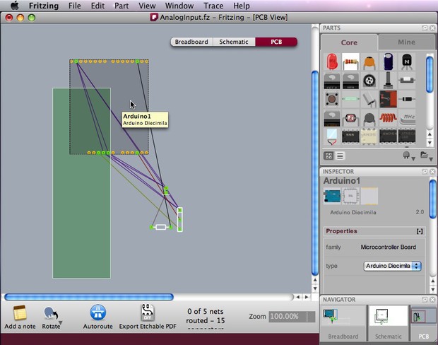
Selecting PCB View in the Navigator will show a completely different illustration of the same circuit. The green rectangle is the board itself, on which parts will be arranged. It is automatically placed as you open a new sketch. Parts are shown as footprints, including the Arduino footprint, and you can identify them by selecting or placing the cursor on them to see their labels. The thin connecting lines are the Rat’s Nest (more about the Rat’s Nest below).
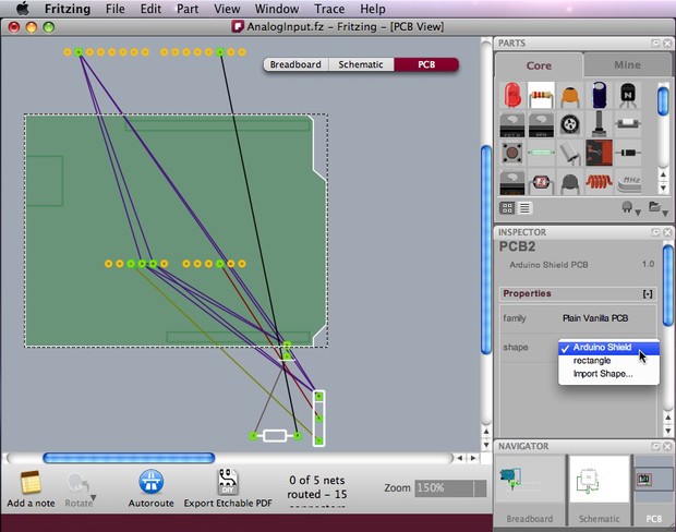
You might want to resize the board, or use an Arduino shield or a board with a custom shape. Select the board and choose/edit your prefered shape in the Inspector.
No need of Hardware to design a circuit with Fritzing:
rong>Fritzing software tool is a free online circuit simulator an ultimate tool that you can use to create an electronic circuit and component diagrams for use with rapid-prototyping developments boards such as the open-source Arduino called Arduino Simulator online.
Introduction:
Fritzing is an open-source hardware initiative that makes electronics accessible as a creative material for anyone.
It is entirely cross-platform and well supported – you can guarantee that it can be used on any Arduino project to show you how to make connections and wire things together using it.
It offers a software tool, a community website, and services in the spirit of Processing and Arduino, fostering a creative ecosystem that allows users to document their prototypes, share them with others, teach electronics in a classroom, and layout and manufacture professional PCBs.
Video credit: Firtzing software tool

Fritzing tool Getting Started
Image Credit: fritzingGettingStart
Download and Start:
Select the download for your platform below.
- Windows32 bit
- Windows64 bit
- Mac OS X7 and up
- Linux32 bit
- Linux64 bit
- SourceGithub
Installation Instructions:
Installing the Fritzing software tool
Please make sure your system satisfies one of these requirements:
Windows – XP and upMac – OSX 10.7 and up, though 10.6 might work tooLinux – a fairly recent linux distro with libc >= 2.6
- Start downloading the Fritzing package that’s right for you.
- Unzip your Fritzing folder somewhere convenient on your hard drive.
- This may also be a good time for you to create a shortcut to the Fritzing application.
- A free unzipping program can be found here, should you need it.
- If you are updating your release of Fritzing, your custom files (parts and bins) are not stored with the application, so they will not be destroyed if you delete the older version of the Fritzing application folder.
- To start Fritzing:
- onWindows: double-click fritzing.exe
- onMac: double-click the Fritzing application
- onLinux: double-click Fritzing, or try ./Fritzing in your shell window
- If you experience problems, please try downloading it again. This often helps. If it doesn’t, have a look at our forums.
Mac notes:
Recent versions of OS X do not allow “unverified” software to be launched directly. In order to run Fritzing, you will need to either:
- right-click the Fritzing icon and select “Open”
- in the warning dialogue, click “Open”
or, to get rid of the warning permanently:
- go to the System Preferences
- open the Security & Privacy page
- unlock it by clicking the lock in the lower-left corner
- set it to allow app downloads from anywhere
Linux notes:
This binary release has been built and tested under Ubuntu 12.04 LTS.
Distros for other flavors of Linux can be found at openSUSE’s repository, at Heinervdm’s openSUSE repo; including a one-click download for openSUSE. Search our forum for even more. Fedora users can install Fritzing with ‘yum install fritzing’.
We heartily thank openSUSE, Thomas Zimmermann, Debian.org, Bruno Canning, the Fedora Project, Ed Marshall, and other people and organizations for making these available. (But please be aware we have not tested these builds.)
Start here to learn all about of Fritzing software tool
Fritzing Learning
Image Credit:
1. Tutorials
Step by step tutorials on how to use Fritzing software tool and produce your own PCBs:
Make sure to check out our YouTube tutorial channel, including the Fritzing Killer Tips and Learning Arduino with the Fritzing Starter Kit.
Breadboard View
- Building a Circuit
- Using a Stripboard(from the video channel)
- Working with SMD parts(from the video channel)
- Creating Paper Templates(from the Blog)
- Curvy Wires and bendable Legs(from the Blog)
PCB View

firtzing pcbview learning
Image Credit:
- Designing a PCB
- One minute Arduino Shield design(from the video channel)
- Double-sided routing(from the Blog)
- How the Autorouter works(from the Blog)
- Explaining the colored lines(from the Blog)
- Custom PCB shapes
- Producing a PCB
- Soldering SMD parts(from the video channel)
Programming
Attaching Programming Code
3. Translations
Parlez-vous français? Sprichst Du Deutsch? Habla Espanol?
Here you can find learning material in other languages than English.
Produce your own board:
With Fritzing Fab you can easily and inexpensively turn your circuit into a real, custom-made PCB. Try it out now!
See also: 7 Top Tips for Taking Advantage of Your New Smart Home
Let us know what you think about the Fritzing Software tool (free online circuit simulator) for Electronics Circuit Design in the comment section below.
If you like this post subscribe to our YouTube Channel for IoT video Tutorials. You can also find us on , and Instagram for more updates.
Want to learn more about Fritzing then visit Fritzing.org
Featured Image Credit:
Information Credit: Fritzing.org
Скачать Fritzing
Программа Fritzing была разработана в Университете прикладных наук в Потсдаме в 2009 году. В настоящий момент есть версии для ОС Windows, Mac OS (10.4 и выше), Linux (2.6 и более поздние версии). Среда разработки переведена на английский, русский, японский, китайский и другие языки. Fritzing имеет простой и интуитивно понятный интерфейс.
 Программу можно загрузить бесплатно с официального сайта
Fritzing можно совершенно бесплатно скачать с официального сайта. Там представлены последние версии дистрибутивов, хотя от предыдущих изданий они отличаются незначительно. Сам процесс вполне прост – пользователем выбирается нужная операционная система и скачивается Fritzing. Процесс установки несложен, нужно следовать указаниям установщика на дисплее.
Настройка программы
После открытия программы можно увидеть 3 режима:
- макетная плата;
- принципиальная схема;
- печатная плата.
 Режим макетная плата
Режим макетная плата используется для создания виртуального проекта. Он будет выглядеть так же, как и реальная схема устройства. Принципиальная схема показывает не реальное изображение, а близкое к традиционному, которое используется инженерами. Она строится автоматически после создания в режиме макетной платы. В последнем режиме можно проектировать и экспортировать нужные данные для получения печатной платы.
Первые шаги
Алгоритм работы в программе:
- создание реальной схемы и анализ ее работоспособности;
- перевод схемы в программу Fritzing, ее редактирование;
- задание нужных характеристик элементам, из которых состоит схема;
- переключение режима работы, каждый из которых может использоваться как основная рабочая среда;
- проектирование печатной платы – есть возможность просмотра макета;
- документирование.
После создания проекта в среде Fritzing его можно реализовывать в реальных условиях.
Программа Fritzing имеет свои библиотеки, помогающие упростить работу. После загрузки имеется ряд установленных библиотек со стандартными компонентами. Существуют библиотеки для различных модулей, шилдов, датчиков, интегральных схем, плат микроконтроллеров. Их можно скачать и установить. Можно добавить новый элемент в библиотеку. Для этого нужно перейти в меню Mine – My parts (Мои компоненты), нажать правой кнопкой мыши на “import” и выбрать нужный файл с разрешением .fzpz, .fbz или .fzbz. После этого он появится в библиотеке. Затем нужно нажать на Mine и выбрать Save Bin для сохранения компонента в программе после завершения работы.
Our Publications
Fritzing Info Brochure (hi-res, low-res)
Other languages: German
Comprehensive description of all things Fritzing
By Uleshka Ascher
Advanced prototyping with FritzingAndré Knörig, Brendan Howell
Studio Description, in Proceedings of Tangible, Embodied and Embedded Interaction 2010, Boston, USA
Fritzing Postcard
Nice flyer used at various events and sometimes shipped with the Starter Kit
General Fritzing presentation
Slides on Fritzing presented at various occassions
SVG in Fritzing: A Case Study
Jonathan Cohen, Brendan Howell, Mariano CrowePaper presented at SVG Open 2009, Mountain View, USAPresentation slides
Tools for Prototyping of Organic UIs
Reto WettachPaper presented at the Workshop on Programming Realities, CHI 2009, Boston, USA.
Fritzing Workflow Poster
A comprehensive poster explaining the how and what of FritzingPoster, presented at Tangible and Embedded Interfaces 2009, Cambridge, UK
Fritzing – A tool for advancing electronic prototyping for designers (ACM)André Knörig, Reto Wettach, Jonathan CohenPaper, in Proceedings of Tangible and Embedded Interfaces 2009, Cambridge, UK
Die Fritzing Online-CommunityJannis LeidelBachelor Thesis, Bauhaus-University Weimar, 2009. (in german)
Design Tools Design: How to design tools for designers, and a proposal of two new tools for the design of physical interactions
André Knörig
Master Thesis, Univ. of Applied Sciences Potsdam, 2008.
Начало работы в Fritzing
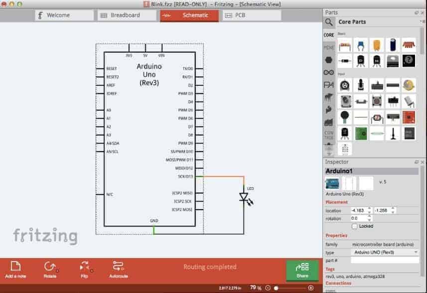
 При первом открытии программы появится окошко Welcome.
При первом открытии программы появится окошко Welcome.
В верхней части есть режимы работы. Если нажать «Макетная плата» появится следующее окно:
Перед тем как начать построение схемы, нужно настроить окружение в соответствии с потребностями пользователя. Для этого нужно перейти в Windows и выбрать те окна, которые будут помещены в окружение. Выбранные окна перетаскиваются в любое место рабочей области.
Далее можно начинать создание схемы в программе. В правой части экрана расположена панель инструментов, в которой хранятся все установленные электронные компоненты, платы и сенсоры. Под ними есть меню, в котором можно отрегулировать параметры (сопротивление резистора, емкость конденсатора).
Чтобы создать свой проект, нужно нарисовать схему. Выбирается нужный компонент из библиотеки Basic и перетаскивается на рабочую часть таким образом, чтобы его выводы совпадали со столбцами на макетной плате. Например, подключение резистора:
Если резистор установлен корректно, столбцы загорятся зеленым цветом. Затем нужно выставить необходимые характеристики устройства. Это делается в правой нижней части в пеню «Инспектор». После выставления нужного сопротивления графически будет указана его верная маркировка цветными кольцами. Компонент можно повернуть на заданный угол – для этого следует щелкнуть правой кнопкой мыши на «повернуть» и выбрать нужный угол поворота. Также этот параметр задается в rotate в боковом меню.
Можно поместить на плату другой компонент. Для создания простейшей схемы питания светодиода потребуется только резистор и сам светоизлучающий диод. Он также выбирается среди набора элементов и устанавливается на схему на несоприкасающиеся зеленые линии.
Затем светодиод и резистор нужно соединить проводами. Для этого курсор наводится на отверстие в плате. Он должен посинеть – это значит, что провод можно подвести в нужную точку. Нужно щелкнуть левой клавишей на отверстие и с зажатой кнопкой довести проводник до нужной точки.
Питание будет производиться от батарейки. Она находится в библиотеке Power и устанавливается на макетную плату. Соединить элементы нужно так, как показано на рисунке ниже.
На вкладке «Принципиальная схема» следует отредактировать полученные соединения к опрятному виду. Путем перетаскивания и поворачивания элементов нужно добиться оптимальной и понятной схемы. Это можно сделать, нажав на клавишу в нижнем левом углу «Автотрассировка».
Чтобы далее использовать схему, ее следует сохранить. Для этого нужно перейти в «Файл» – «Экспорт» – As image, выбрать нужный формат и название и сохранить документ.
В программе можно самостоятельно создавать новый элемент или модернизировать существующий. Второй способ более простой. Для этого нужно выбрать подходящий элемент из библиотеки и перетащить его в рабочую область. Затем запускается редактор компонента – для этого требуется кликнуть на элементе и выбрать Edit (new parts editor). Появится вкладка с редактированием Breadboard. Также появятся другие вкладки, в которых задаются нужные параметры для нового элемента. Всего 6 основных разделов редактирования: макетная плата, принципиальная схема, печатная плата, иконка, metadata, соединения.
Для создания объекта с нуля вся сложность будет заключаться в графике компонента. Редактируется векторная графика во внешнем редакторе, поддерживающем формат svg. Можно найти базовые шаблоны компонентов в интернете, отредактировать их в любой программе и загрузить в Fritzing.
Free electronic design automation software
Fritzing is a free design application that works to support designers and artists as they work with interactive electronics. This open-source program is a comprehensive and functional design automation tool that can help users create electronic designs from scratch. It allows you to work creatively with interactive electronics and document their Arduino-based prototypes. Moreover, it is a great program to learn how to use printed circuit boards (PCB) and get efficient with them.
What does the app offer?
Fritzing is primarily meant to function as a teaching instrument for users to learn how to create and work with PCBs and other electronics. In its main window, you can see three viewing modes. There is the Breadboard, which is where users begin their work. Here, you can create a circuit that mimics the real thing. With this, you can prevent mistakes when turning your project from a virtual state to a physical object.
The Schematic mode, meanwhile, shows you the circuit design as a diagram. This can be helpful for users who prefer standard circuit symbols. Finally, the PCB view lets you design and export documents required to produce the PCB. More than the virtual modes, it also boasts an extensive Part Library. The available parts are organized into categories, such as All parts, Mine, and Core. Adding the parts to your design is as easy as dragging them from the library and dropping them into your project.
There is also a Part Inspector available, where users can view and modify the information on the individual circuit parts. Another interesting feature of this handy utility is its ability to make customized parts. You only need to enter the part name, icon, and a graphic image, which they will use in the chosen view mode. You also need to provide other required specifications, such as label, description, properties, tags, and author.
Professional-grade electronic design
On an ending note, Fritzing is an interesting and reliable app for designers and engineers. It allows users to automate electronics design, test their ideas, and develop PCBs for their electronics. It also enables users to share their prototypes with others effortlessly, thereby making it an effective tool to teach electronics in the classroom. However, note that the developers have stopped updating the app. There is a small community of developers working on it. But it may not be enough to keep it from being faced out.
Hand-routing
Use any of the following methods to hand-route traces and jumpers:
- The safest way is to right-click a Rat’s nest wire and choose «Create Trace from Selected Wire(s)» or «Create Jumper from Selected Wire(s)». This will avoid making any changes in the circuit that you built in Breadboard View.
- Another way is to simply click a part’s connector, and drag to make a connection. A trace will be created. To create a jumper, just right-click on the trace and choose «Create Jumper from Selected Wire(s)». To avoid incorrect wiring, we strongly recommend you follow the Rat’s nest wire connections while using this method.
Note that while clicking and holding on a connector, all equipotential connectors are highlighted (in yellow). This shows the whole set of connections attached to this particular connection, and can really help to make hand-routing decisions. Once again, take good care not to cross wires!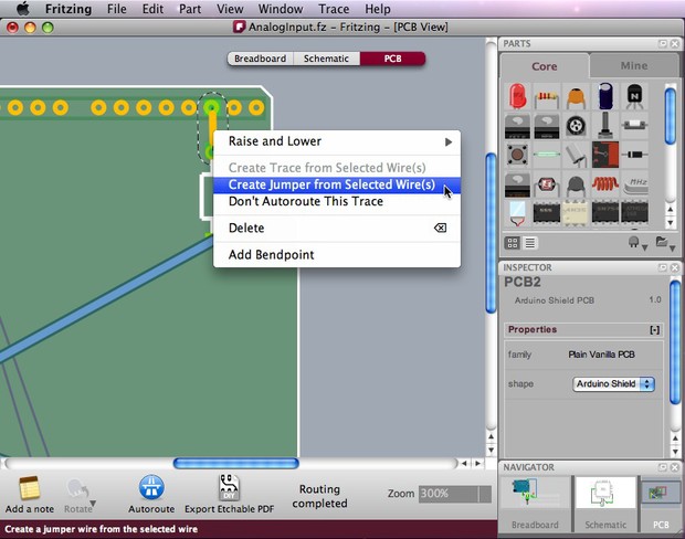
Создаем SVG-файл макета компонента
Если вы хотите сделать корпус для интегральной схемы, то редактор компонентов Fritzing (new parts editor) позволяет легко создавать собственные микросхемы, и в этом случае вам не нужно будет использовать како-то сторонний графический векторный редактор.
Если вам удастся найти в своей библиотеке готовый элемент, который очень похож на тот который вам нужен, то разумно будет использовать его в качестве основы для создания нового компонента Fritzing.
Я нашел подходящий компонент в стандартной библиотеке Fritzing — это LCD screen.
LCD screen в библиотеке
Щелкаем правой кнопкой мыши и выбираем Edit Part. Выбранный элемент откроется в редакторе компонентов.
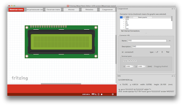
В нижнем правом углу этого окна можно видеть имя файла lcd-GMD1602K.svg. Пользуясь поиском в вашей ОС можно определить его местонахождение. У меня это:
Fritzing.app/Contents/MacOs/parts/svg/core/breadboard/lcd-GMD1602K.svg
Далее открываем этот файл в своем графическом редакторе (у меня это Incscape) и сохраняем его где-нибудь у себя на диске под новым именем. Процесс редактирования в графическом редакторе выходит за рамки моего повествования, поэтому я остановлюсь только на некоторых важных деталях.
Компонент рисуется в масштабе 1:1.
В файле удобно сделать несколько слоев: design, copper, breadboard.
Вот как выглядят элементы на каждом из этих слоев.
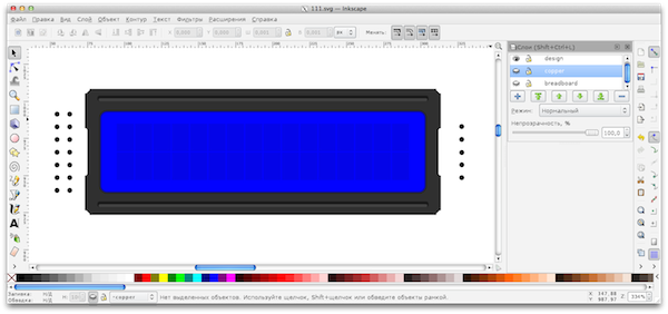
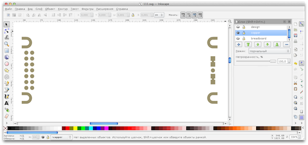
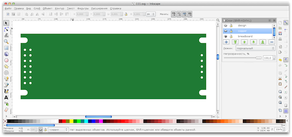
А вот так все три слоя вместе.
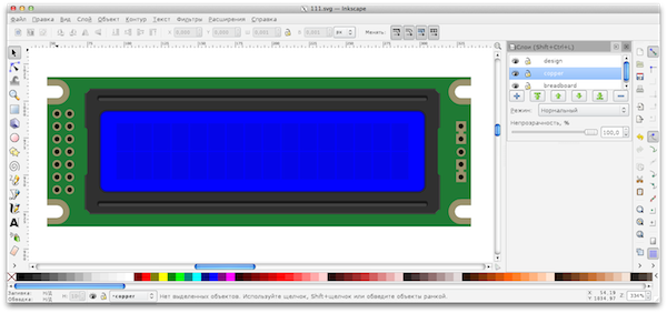
Скачать готовый SVG-файл с макетом LCD экрана WH1602D.
WH1602D WH1602D.svg
1.2 MiB 386 Downloads
| Category: | Fritzing |
| Date: | 11.07.2014 |
Если же похожего элемента в библиотеке Fritzing найти не удалось, то еще одним способом облегчить себе жизнь, является использование в качестве базового шаблона файла datasheet в формате PDF, предоставляемого производителем этого элемента. В файле формата PDF, как правило, содержится уже векторный чертеж нашего элемента и для того, чтобы им воспользоваться, мы должны импортировать его в своем графическом редакторе. Конечно, затем придется еще потрудиться, чтобы довести его до ума, но, тем не менее, это очень хороший способ сэкономить себе время.
Скачать datasheet для Winstar WH1602D
WH1602D WH1602D.pdf
430.1 KiB 278 Downloads
| Category: | Documents |
| Date: | 11.07.2014 |
При разработке макета элемента желательно использовать цвета, которые являются стандартными для изображений компонентов:
HEX: 9A916C, RGB: 154 145 108
Используется для изображения контактных площадок и медных проводников
HEX: 8C8C8C, RGB: 140 140 140
Если есть какие-то элементы на печатной плате, лучше использовать серый цвет
Вы можете скачать архив, в котором содержатся шаблоны и шрифты для соответствия ваших элементов стандартам Fritzing.
Fontsandtemplates Fritzing fontsandtemplates_fritzing.zip
369.3 KiB 550 Downloads
| Category: | Fritzing |
| Date: | 11.07.2014 |
В этом файле содержится:
- Шрифт Droid Sans
- Шрифт ORC-A
- Шаблон элемента для макетной платы
- Шаблон схематического изображения компонента
- Шаблон Печатной платы компонента
Размер шрифта нужно выбирать равным 5pt, а там где необходимо сделать особо мелкие надписи можно использовать и 3pt.
Как установить шрифты в Mac OS X рассказано здесь.
Commercial Tools
VirtualBreadboard
A simple simulation tool for microcontroller circuits also based on a loose breadboard metaphor. It’s possible to simulate the PIC or BasicStamp2 and offers a dev kit to program more components.Platforms: Windows License: Academic/Personal (15-30€)Potential Might be a model for simulation, if we want that.
VeeCAD
Not for PCB, but for stripboard design — and thus also interesting for prototyping when you want to start with a schematic diagram. I also like the graphics.Platforms: Windows License: Free, Commercial (20€)Potential: Should be supported and mentioned by Fritzing
ExpressPCB
Offers free software with their PCB manufacturing service. Interesting because it is possible to get a quote and order from inside the software.Platforms: Windows License: Free Potential: Similar service would be great: Upload the design to the website for feedback and join others to order together.
Auto-routing
After positioning all parts on the board, be aware that parts are not really connected to each other yet. The thin connecting lines that you see (Rat’s Nest Layer) only act as a guideline. We would now want Fritzing to automatically generate the connection traces between parts. Click the Auto-route function from the bottom menu bar.
If you notice that Fritzing is struggling trying to generate a connection, you can press the «Skip this Trace» button or «Cancel Auto-routing» in the bottom menu while in process.
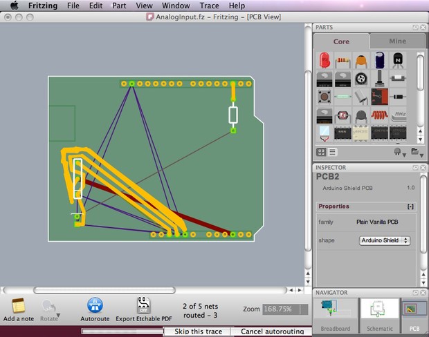
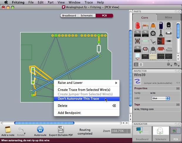
Such a problem might happen because parts were not arranged properly on the board or when there is just no possible route. You will then need to Hand-route the trace (more about hand-route below) or create a jumper. Jumpers are connections that need to be soldered with external wires. These are shown as blue connections while traces are shown as orange ones. In the screenshot below, two jumper wires were created after the routing between connectors failed.
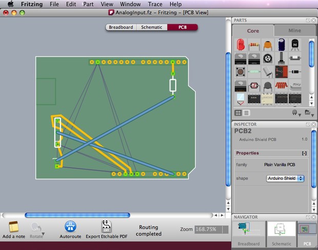
If you are happy with some of the traces and want to keep them untouched, or you know in advance that some connections need jumpers, you might want to tell Fritzing to exclude some connections in the auto-routing process. To do so, select the connections you want to exclude, choose «Don’t Autoroute this trace» in the right-click menu or in the Trace menu. Only then press Auto-route. The selected traces will be left untouched while all other connections will be auto-routed. Any traces that were handrouted are automatically marked as «Don’t Autoroute.»
Be aware that if you moved a part after auto-routing or hand-routing, the routing traces are not corrected automatically. You will need to be cautious when moving parts and make sure you don’t create any short circuits.
Videos
(German)Talk at Creative Coding, Bayreuth, 2010
Reto Wettach on democratizing hardware (German, Audio only)Interview at breitband, DeutschlandRadio Kultur, Dec 2009
Reto Wettach on why Fritzing is important for designersTalk at UID Fall Summit, Umea, Nov 2009
André Knörig on Fritzing’s history and visionTalk at UID Fall Summit, Umea, Nov 2009
Fritzing Introduction (German version)Nice Teaser Video by Stefan Hermann, Sep 2009
Starting with Arduino (Part 2)Beginner’s tutorial by Stefan Hermann using Fritzing, Mar 2009
Reto Wettach on democratizing production of electronicsPanel discussion at Transmediale, Berlin, Jan 2009
Dirk van Oosterbosch on Fritzing’s UI designTalk at ThisHappened.nl, Utrecht, Nov 2008